
Mixed flow fan and motor

A fan and mixed flow technology, applied in the direction of electrical components, electromechanical devices, electric components, etc., can solve the problems of low wind pressure, unsatisfactory demand, large flow, etc., and achieve the effect of reasonable design and good practical application value

Inactive Publication Date: 2019-11-01
CRRC YONGJI ELECTRIC CO LTD
View PDF5 Cites 1 Cited by
  • Summary
  • Abstract
  • Description
  • Claims
  • Application Information

AI Technical Summary

Problems solved by technology

Axial fans such as image 3 As shown, the axial flow fan is characterized by large flow rate and low wind pressure, which is suitable for cooling motors with low wind resistance. The installation of axial flow fans often cannot meet the needs, and even backfires, resulting in little difference between the installation of the fan and the absence of the fan.
[0004] For 3.X~4.XMW high-power double-fed motors, because of their low speed and high power loss, the original ventilation structure is difficult to meet the requirements of ventilation and heat dissipation, and fans that can provide large air pressure and air volume are needed

Method used


Image

  • Mixed flow fan and motor
  • Mixed flow fan and motor
  • Mixed flow fan and motor

Examples


Embodiment Construction

[0019] Specific embodiments of the present invention will be described in detail below in conjunction with the accompanying drawings.

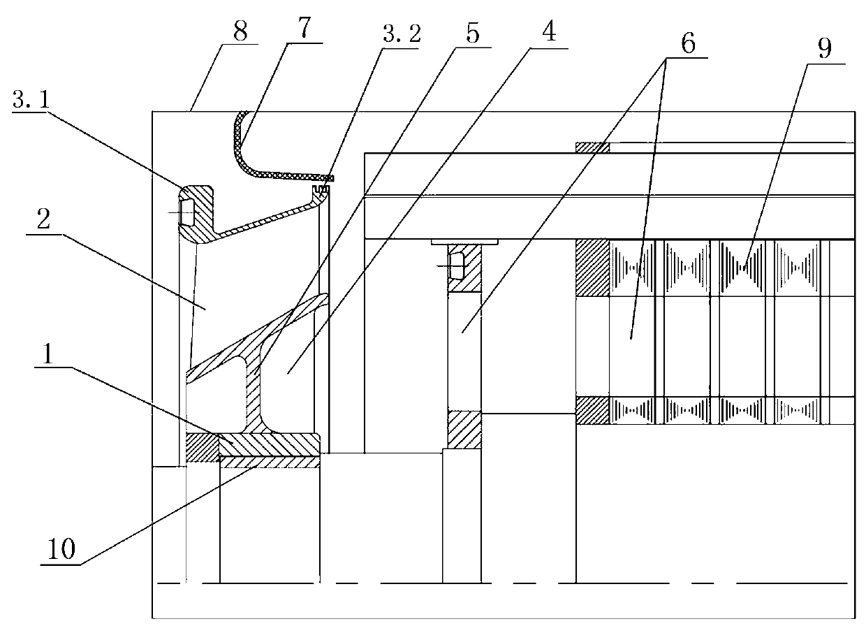
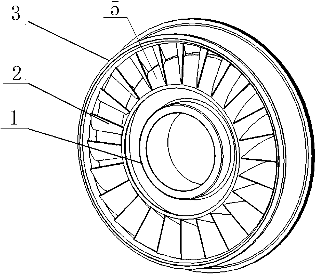
[0020] A mixed-flow fan includes an impeller hub 1, blades 2, a wheel cover 3 and a wheel disc 5.

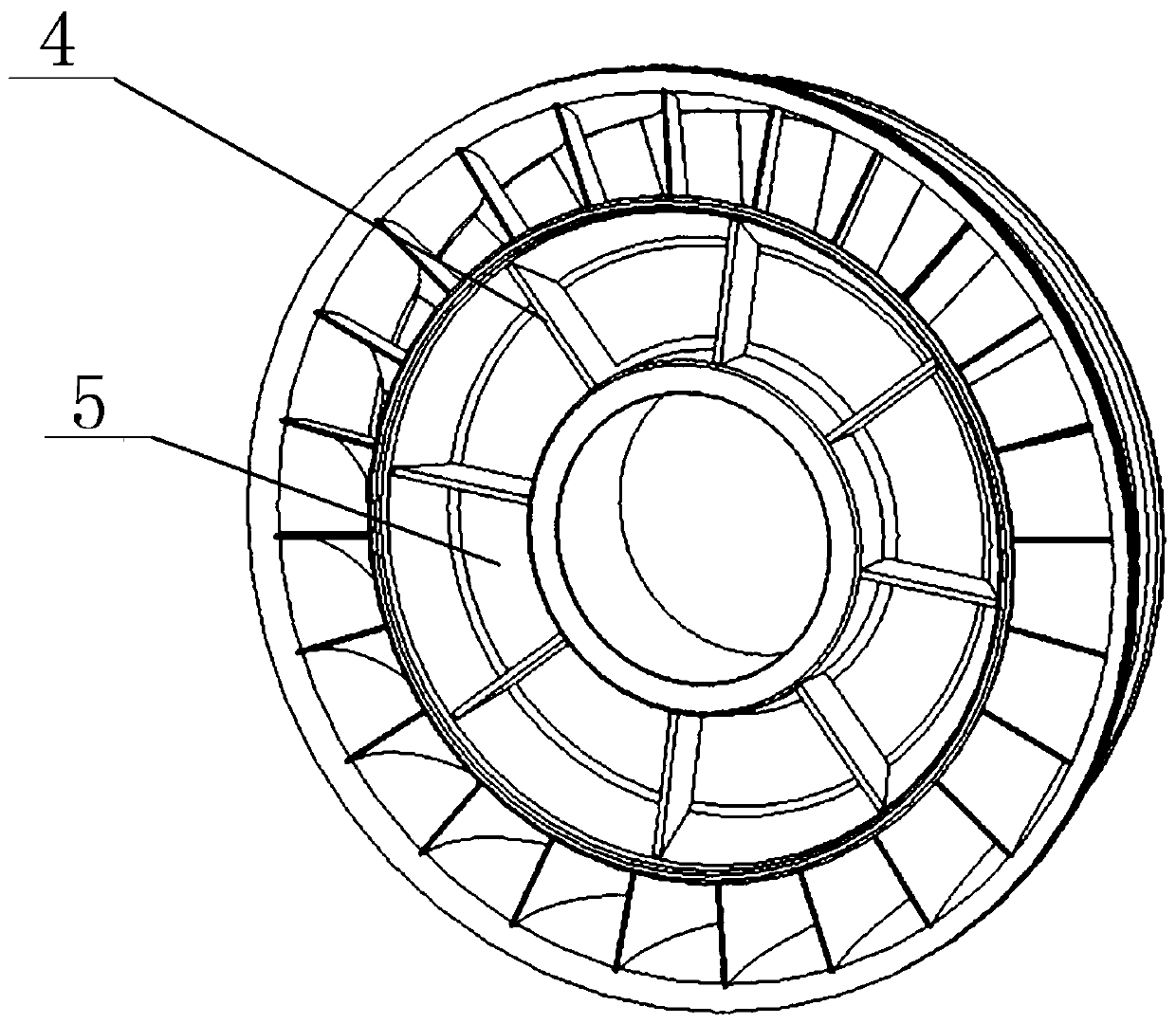
[0021] Such as Figure 2a , 2b As shown, the impeller hub 1 is integrally equipped with a wheel 5, the surface of the wheel 5 is inclined, that is, the surface of the wheel is conical, the small end of the wheel 5 is used as the air inlet end, and the large end is used as the air outlet. Between the wheel disc 5 and the wheel cover 3 there are even inherent blades 2, and the air outlet geometric angle of the blades 2 is equal to 90°. The inner surface of the wheel cover guide end 3.1 of the wheel cover 3 adopts a lip structure, and the outer surface of the wheel cover sealing end 3.2 of the wheel cover 3 adopts a comb-tooth sealing structure. Radial fins 4 are arranged inside the wheel disc 5 .

[0022] Such as figure 1 As shown, a motor o...


PUM


Abstract

The invention discloses a mixed flow fan and a motor. The mixed flow fan comprises an impeller hub (1), blades (2), a wheel cover (3) and a wheel disc (5), the wheel disc (5) is arranged at the outerportion of the impeller hub (1), the surface of the wheel disc (5) is beveled, and the blades (2) are uniformly fixed between the wheel disc (5) and the wheel cover (3). The motor comprises a base (8), a rotor structure (9), a rotor axial vent (6) and a rotating shaft (10), and the mixed shaft fan is installed at the end of the rotating shaft (10). The new mixed-flow fan structure was tested and verified on a certain type of motor product of the company. The test results and the motor ventilation and heat dissipation effect are obvious, the air volume of the mixed flow fan increases 60% compared to a general axis fan, 4.XMW motor is subjected to temperature rise about 67K, and therefore, the mixed flow fan and the motor are especially suitable for low-speed (1200r / min) and high-power air-to-air cold wind turbines.

Description

technical field [0001] The invention belongs to the field of motors, in particular to a mixed-flow fan, which is suitable for high-power, low-speed, self-ventilating double-fed wind power generators, as well as other types of motors, and is especially suitable for self-ventilating cooling motors with a fan installed on the internal shaft of the motor. Background technique [0002] Air-to-air-cooled doubly-fed wind turbines generally adopt self-ventilation (IC616) or forced-ventilation (IC666) cooling methods, and 1.5MW~2.XMW air-to-air-cooled doubly-fed generators use self-ventilation cooling methods for rotors, and axial fan cooling methods are often used, or The centrifugal fan cooling structure is adopted, and the fan rotates with the rotor to generate wind pressure and air volume, which takes the internal heat out to the air cooler for heat exchange; the higher the speed, the greater the wind pressure and air volume, and the better the cooling effect. The forced ventilat...

Claims


Application Information

Patent Timeline
IPC IPC(8): H02K9/06
CPCH02K9/06
Inventor 张广兴苏莫明刘军婷霍永强崔皓
Owner CRRC YONGJI ELECTRIC CO LTD
Learn More