Valve core oil coating device

A technology of oiling device and valve core, which is applied to the device and coating of the surface coating liquid, which can solve the problem of low efficiency of manual oiling of the valve core, and achieve the effect of saving labor costs and high oiling efficiency

Pending Publication Date: 2019-11-05
深圳市佳宇精密机电科技有限公司
View PDF0 Cites 4 Cited by
  • Summary
  • Abstract
  • Description
  • Claims
  • Application Information

AI Technical Summary

Problems solved by technology

[0003] The purpose of the present invention is to solve the prob

Method used


Image

  • Valve core oil coating device
  • Valve core oil coating device
  • Valve core oil coating device

Examples


Embodiment Construction

[0023] The structure of the present invention will be further described below in conjunction with the accompanying drawings.

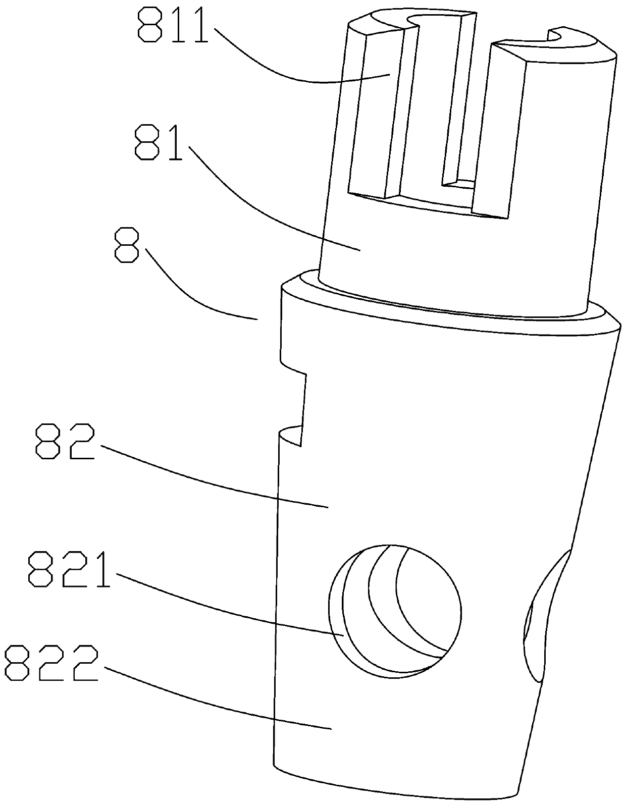
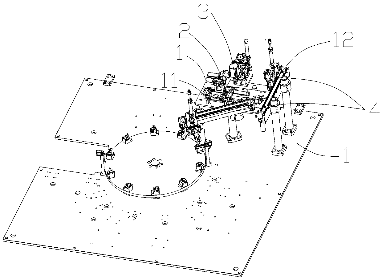
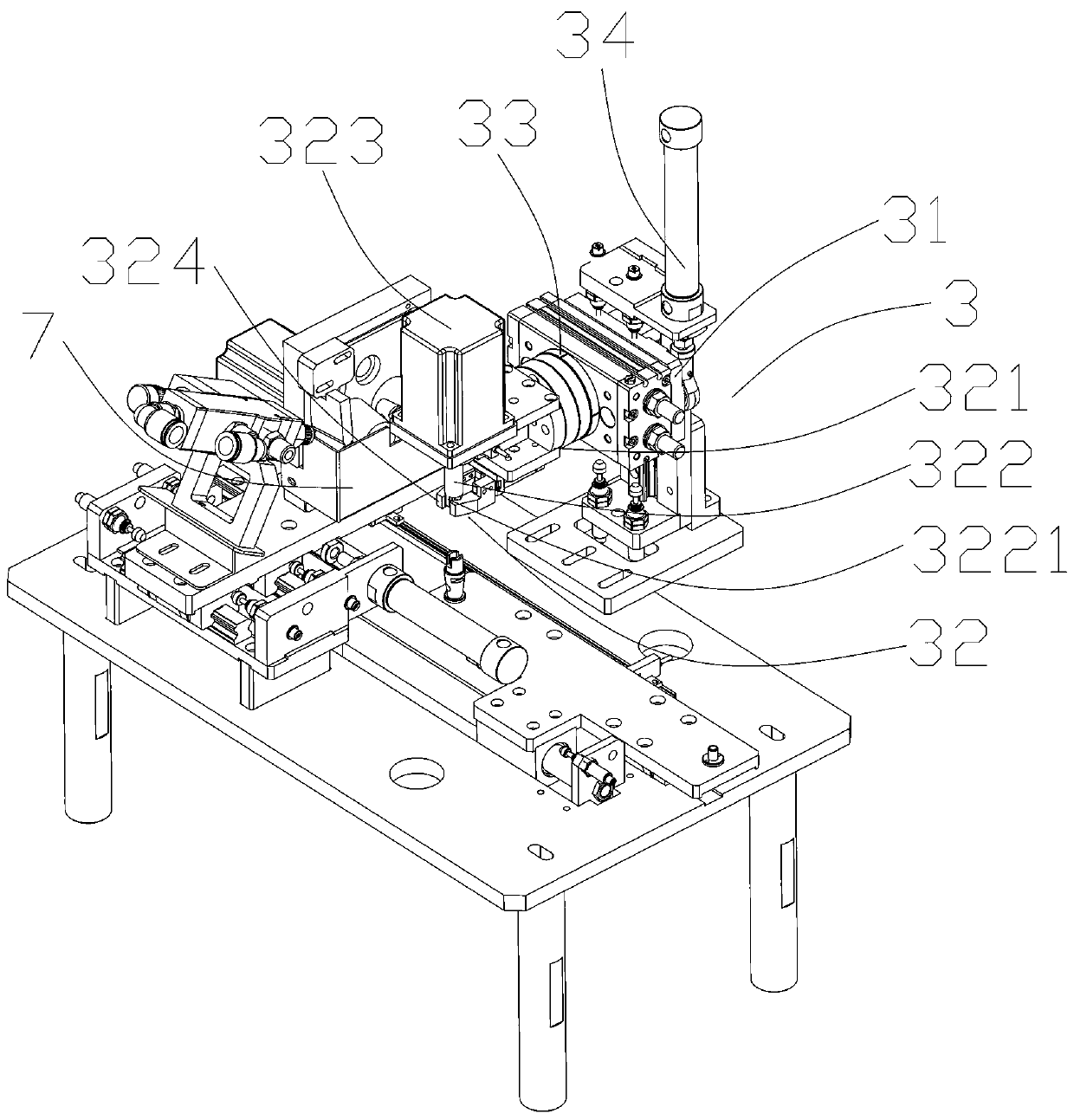
[0024] refer to Figure 1 to Figure 7 , a valve core oiling device includes a frame 1, a valve core oiling mechanism 2 for oiling the valve core on the frame, and a valve core feeding mechanism for feeding the valve core oiling mechanism. Mechanism 3, and the spool feeding mechanism 4 that feeds to the spool feeding mechanism; the spool feeding mechanism 3 includes a feeding support plate 31 located on the frame, a spool feeding clamping mechanism 32, and Drive the spool loading and clamping mechanism to rotate the first rotary cylinder 33 for feeding, and the spool loading and clamping mechanism 32 includes a feeding rotating plate 321 connected to the first rotary cylinder for extending into the notch at the end of the spool The tail support rod 322 that supports the tail of the spool, the tail support rod drive motor 323 that drives the rotation of...


PUM


Abstract

The invention relates to a valve core oil coating device. The device solves the problem that an existing valve core is low in manual oil coating efficiency. The device comprises an machine frame, a valve core oil coating mechanism, a valve core feeding mechanism, a valve core supplying mechanism, wherein the valve core oil coating mechanism is arranged on the machine frame and is used for coatingoil on a valve core, and the valve core feeding mechanism is used for feeding for the valve core oil coating mechanism; the valve core feeding mechanism comprises a feeding supporting plate, a valve core feeding clamping mechanism and a first rotating air cylinder, wherein the feeding supporting plate is arranged on the machine frame, the first rotating air cylinder are used for driving the valvecore feeding clamping mechanism to rotate and feed; and the valve core oil coating mechanism comprises an oil coating wheel mechanism which is used for coating oil to the valve core through rotation,an oil suction wheel which is opposite to the oil coating mechanism and is used for coating oil to the oil coating wheel mechanism, a point oil mechanism used for spraying oil to the oil suction wheel, and a scraping plate used for scraping and coating the oil on the oil suction wheel. According to the device, the valve core feeding mechanism is used for feeding and transferring the valve core, the valve core feeding mechanism is used for automatic feeding of the valve core, the valve core oil coating mechanism is used for automatically coating the valve core, so that automatic oil coating ofthe valve core is realized, the oil coating efficiency is high, and the labor cost is saved.

Description

technical field [0001] The invention relates to the field of mechanical equipment, in particular to a valve core oiling device. Background technique [0002] The spool 8 is a hollow seal of soft rubber. The tail 81 of the spool is provided with a gap 811, and the two sides of the head 82 of the spool are provided with through holes 821. The spool should be installed outside the head of the spool during use. 822 oiling, the existing spool oiling is usually manual oiling, the efficiency is low, and it is not suitable for mass production. Contents of the invention [0003] The purpose of the present invention is to solve the problem of low manual oiling efficiency of the existing valve core. [0004] The technical scheme adopted for solving the technical problems proposed by the present invention is: the valve core oiling device of the present invention includes a frame, and the valve core oiling mechanism for oiling the valve core is arranged on the frame, and is used for ...

Claims


Application Information

Patent Timeline
IPC IPC(8): B05C1/02B05C13/02
CPCB05C1/02B05C13/02
Inventor 康怀旺
Owner 深圳市佳宇精密机电科技有限公司
Why Eureka
Try Eureka