
Taper drill reamer

A drilling reamer and taper technology, which is applied in the direction of drill repair, drilling tool accessories, drilling/drilling equipment, etc., can solve the problems of reduced strength of the tapered edge, inability to meet fine reaming, and reduce the extrusion effect of the hole wall. , to achieve the effect of improving processing quality, reducing processing cycle time and increasing chip breaking ability

Inactive Publication Date: 2019-11-05
ZHUZHOU CEMENTED CARBIDE CUTTING TOOLS CO LTD
View PDF12 Cites 2 Cited by
  • Summary
  • Abstract
  • Description
  • Claims
  • Application Information

AI Technical Summary

Problems solved by technology

However, the drill adopts two chip removal grooves, and the tapered cutting edge part is also two chip removal grooves, which will reduce the strength of the tapered edge part, and it is easy to generate vibration during processing, forming vibration lines on the surface of the hole wall; gradually narrowing Although the side edge structure can reduce the cutting force to a certain extent, it correspondingly reduces the extrusion effect on the hole wall, so the surface quality of the drill bit is low, which can only meet the drilling and expansion processing, and cannot meet the requirements of fine reaming processing.

Method used


Image

  • Taper drill reamer
  • Taper drill reamer
  • Taper drill reamer

Examples


Embodiment Construction

[0026] The present invention will be described in further detail below in conjunction with the accompanying drawings and specific embodiments.

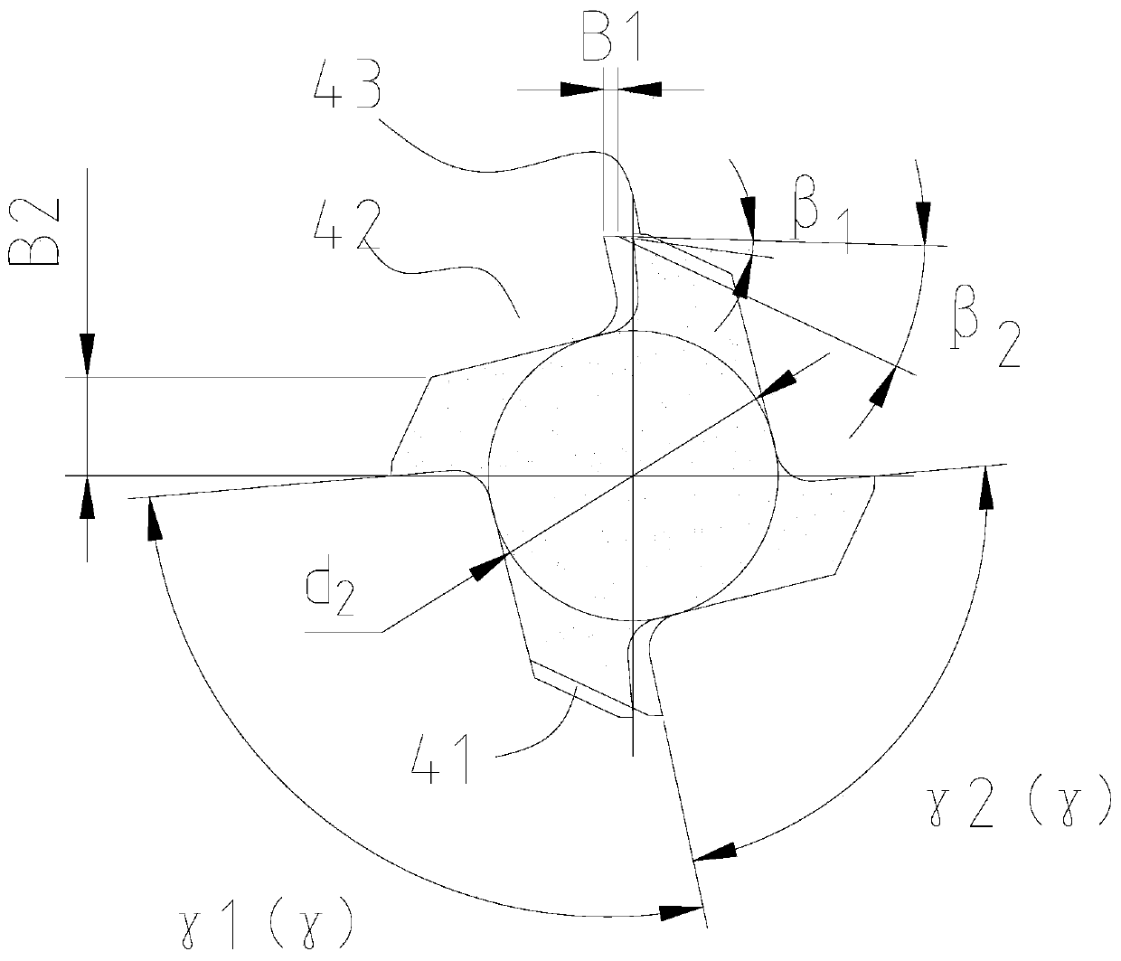
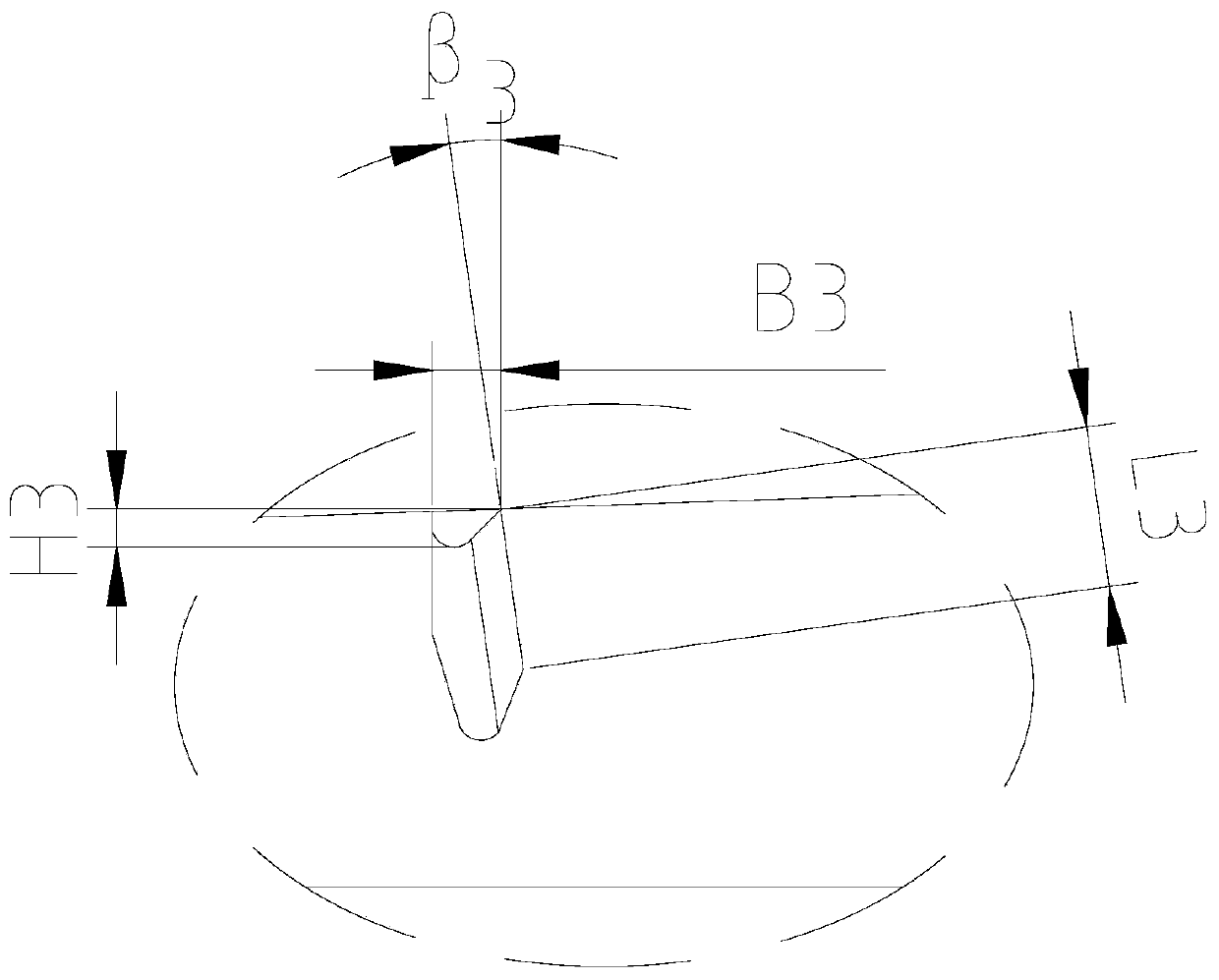
[0027] Such as Figure 1 to Figure 5 As shown, the tapered drill reamer of the present embodiment includes a cutting part and a handle 1, and the cutting part includes a drilling part 2, a neck part 3 and a tapered cutting part 4 arranged in sequence, and the tapered cutting part 4 is connected with the handle 1, The drilling part 2 includes two drilling lobes 21 and two drilling flutes 22 arranged between the two drilling lobes 21, the end surface of the drilling lobes 21 is provided with a drill point 201 and The peripheral surface is provided with a secondary edge 202, and the tapered cutting part 4 includes four tapered blades 41 and four tapered chip flutes 42, the drilling chip flutes 22 and the tapered chip flutes 42 all extend to the neck 3, and the drill The axial distance between the drilled chip flute 22 and the tapered ch...


PUM


Abstract

The invention discloses a taper drill reamer. The taper drill reamer comprises a cutting part and a handle part, wherein the cutting part comprises a drilling part, a neck part and a taper cutting part which are sequentially arranged, and the taper cutting part is connected with the handle part; the drilling part comprises two drilling blades and two drilling chip removal grooves arranged betweenthe two drilling cutting blades, a drill tip is arranged on the end face of each drilling blade, and an auxiliary blade is arranged on the circumferential surface of each drilling blade; the taper cutting part comprises at least three taper blades and three taper chip removal grooves; the drilling chip removal grooves and the taper chip removal grooves extend to the neck part; and the axial distance between the drilling chip removal grooves and the taper chip removal grooves are L, wherein L is larger than 0. According to the taper drill reamer, the drilling part and the taper cutting part areseparated through the neck part, the taper cutting part can provide with more than three taper chip removal grooves and does not need to correspond to the drilling part, on the basis that the core thickness of the taper cutting part is increased, the chip removal requirement is met by increasing the number of the taper chip removal grooves, so that the strength of the taper cutting part is increased, the anti-seismic capability of the cutter is increased, and generation of vibration grains is reduced.

Description

technical field [0001] The invention relates to a metal cutting tool, in particular to a taper drill reamer. Background technique [0002] In the metal cutting industry, the concentricity of the taper hole of the knuckle arm and the surface quality of the hole wall are relatively high, which is relatively difficult to machine. The conventional process is to drill the bottom hole with ordinary twist first, then use a taper reaming tool for semi-finishing to remove the allowance, and finally use a fine reamer to process it in place. With the development of cutting technology, customers have higher and higher requirements on the processing cycle of parts. Single-function tools are often difficult to meet the requirements, so compound processing tools are needed. [0003] The patent document with the notification number CN201520334391 discloses a taper drill bit for a steering knuckle taper hole. The drill is provided with a straight cutting portion and a tapered cutting edge...

Claims


Application Information

Patent Timeline
Patent Type & Authority Applications(China)
IPC IPC(8): B23B51/08
CPCB23B51/08B23B2251/40
Inventor 卞玲玲张海罗胜聂超
Owner ZHUZHOU CEMENTED CARBIDE CUTTING TOOLS CO LTD
Learn More