Spiral conveyer fault automatic repair device and method

A screw conveyor, automatic repair technology, applied in the direction of the conveyor control device, conveyor, conveyor objects, etc., can solve the problem that the material blockage cannot be detected in time

Pending Publication Date: 2019-11-05
HUBEI TIANYI MACHINERY CO LTD
View PDF0 Cites 1 Cited by
  • Summary
  • Abstract
  • Description
  • Claims
  • Application Information

AI Technical Summary

Problems solved by technology

It solves the technical problem that the material blockage in the prior art cannot be discovered in time, and even if it is found, it needs to be shut down and the on-site staff will open the equipment to dig out the blocked material

Method used


Image

  • Spiral conveyer fault automatic repair device and method
  • Spiral conveyer fault automatic repair device and method

Examples


Embodiment Construction

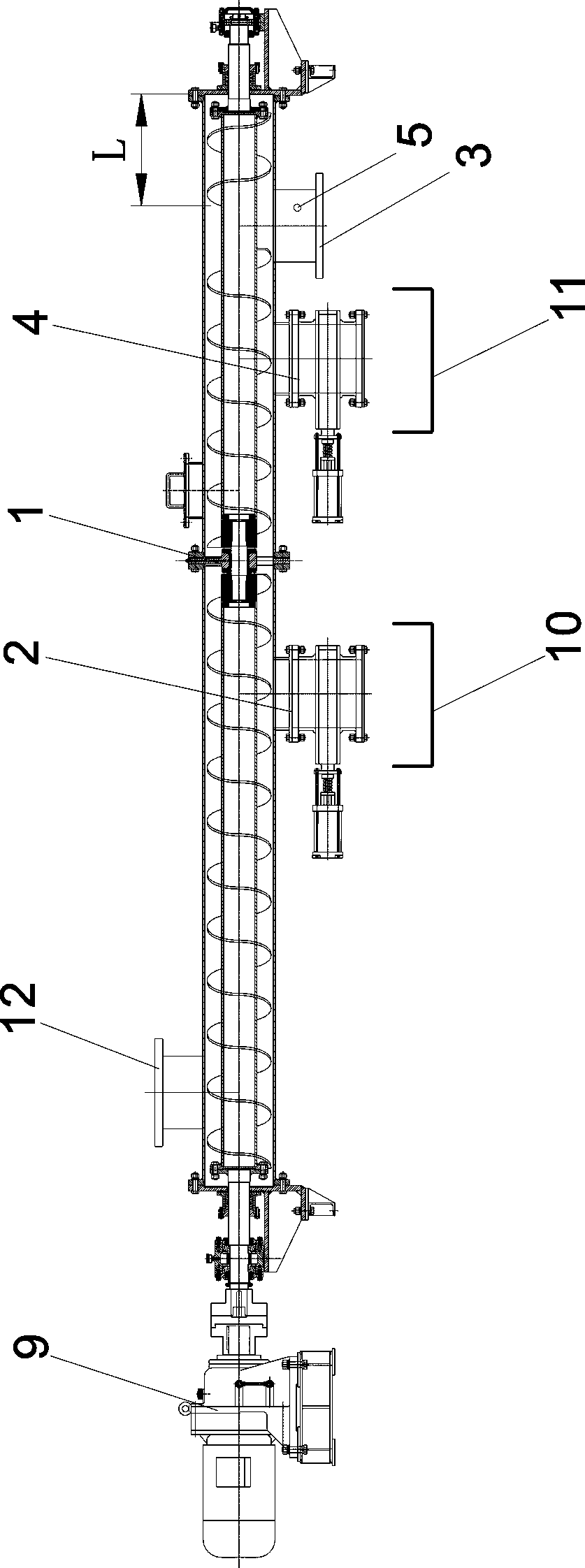
[0022] like figure 1 , figure 2 As shown, the screw conveyor fault automatic repair device, the device includes:

[0023] The first pneumatic gate 2 arranged on the feeding side of the hanging bearing 1 of the screw conveyor;

[0024] A second pneumatic gate 4 arranged on the feed side of the discharge port 3 of the screw conveyor;

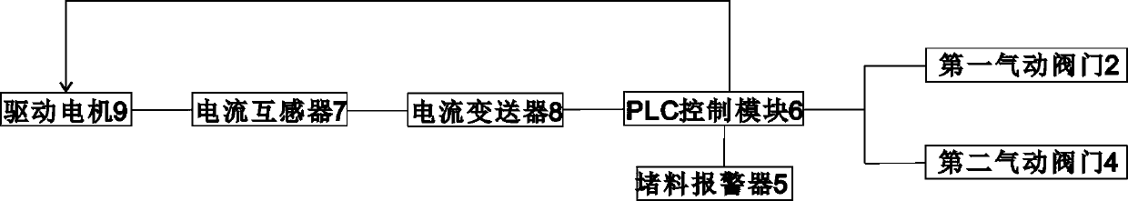
[0025] PLC control module 6, current transformer 7, current transmitter 8 arranged in the control cabinet; the drive motor 9 of the screw conveyor is connected to the current transformer 7, the current transformer 7 is connected to the current transmitter 8, and the current transmitter 8 Connect the PLC control module 6;

[0026] The PLC control module 6 is respectively connected to the drive motor 9 , the first pneumatic gate 2 , the second pneumatic gate 4 and the material blocking alarm 5 .

[0027] A first feeding chute 10 is provided below the first pneumatic gate 2 , and a second feeding chute 11 is provided below the second pneumatic g...


PUM


Abstract

Disclosed are a spiral conveyer fault automatic repair device and a spiral conveyer fault automatic repair method. The spiral conveyer fault automatic repair device comprises a first pneumatic gate arranged on a feeding side of a hanging bearing of a spiral conveyer and a second pneumatic gate arranged on a feeding side of a discharging port of the spiral conveyer, and further comprises a PLC (programmable logic controller) control module, a current transformer and a current transmitter which are arranged in a control cabinet, wherein a drive motor of the spiral conveyer is connected with thecurrent transformer, the current transformer is connected with the current transmitter, the current transmitter is connected with the PLC control module, and the PLC control module is respectively connected with the drive motor, the first pneumatic gate, the second pneumatic gate and a material blockage alarm. The spiral conveyer fault automatic repair device and the spiral conveyer fault automatic repair method perform real-time monitoring feedback and automatic judgment on a material blockage problem of the spiral conveyer, and performs repair. The spiral conveyer fault automatic repair device and the spiral conveyer fault automatic repair method solve the technical problems that a material blockage situation cannot be timely discovered, and needs field personnel to shut down the spiralconveyer and open the spiral conveyer for drawing and digging blocked materials even if discovered in the prior art.

Description

technical field [0001] The invention relates to the technical field of fault diagnosis of screw conveyors, in particular to an automatic fault repairing device and method for screw conveyors. Background technique [0002] The screw conveyor is divided into U-shaped screw conveyor and tubular screw conveyor in appearance. The working principle of the screw conveyor is that the rotating screw blade pushes the material for screw conveying. The force that keeps the material from rotating with the screw conveyor blades is the weight of the material itself and the frictional resistance of the screw conveyor casing to the material. The spiral blade is welded on the rotating shaft of the screw conveyor. The surface type of the blade has solid surface type, belt type surface type, blade surface type and other types according to the different materials to be conveyed. The screw shaft of the screw conveyor is provided with a thrust bearing at the end of the material moving direction ...

Claims


Application Information

Patent Timeline
Patent Type & Authority Applications(China)
IPC IPC(8): B65G33/24B65G43/08B65G33/34
CPCB65G33/24B65G33/34B65G43/08B65G2203/042
Inventor 黄俊杰万厚兵王名飞
Owner HUBEI TIANYI MACHINERY CO LTD
Why Eureka
Try Eureka