
Material conveying device and material conveying method

A material conveying and belting technology, which is applied in the directions of transportation and packaging, thin material handling, winding strips, etc., can solve problems such as unstable friction and traction, tearing of products, stretching deformation, and affecting the stability of conveying materials. To achieve the effect of stable transmission

Inactive Publication Date: 2019-11-05
HANS LASER TECH IND GRP CO LTD
View PDF6 Cites 0 Cited by
  • Summary
  • Abstract
  • Description
  • Claims
  • Application Information

AI Technical Summary

Problems solved by technology

[0002] With the development of modern industry, flexible material roll products have higher and higher requirements for laser marking automation, but in the automatic production process, some material rolls are processed by laser processing, and the processing of material rolls is carried out in sections , during the segmental feeding process, the flexible coil material will be continuously accelerated, decelerated, and stopped. Risks such as tearing and stretching deformation will lead to unstable friction and traction of the coil on the material roller, which will affect the stability of the conveying material

Method used


Image

  • Material conveying device and material conveying method
  • Material conveying device and material conveying method
  • Material conveying device and material conveying method

Examples


Embodiment Construction

[0023] In order to facilitate the understanding of the present invention, the present invention will be described more fully below with reference to the associated drawings. Preferred embodiments of the invention are shown in the accompanying drawings. However, the present invention can be embodied in many different forms and is not limited to the embodiments described herein. On the contrary, the purpose of providing these embodiments is to make the disclosure of the present invention more thorough and comprehensive.

[0024] It should be noted that when an element is referred to as being “fixed” to another element, it can be directly on the other element or there can also be an intervening element. When an element is referred to as being "connected to" another element, it can be directly connected to the other element or intervening elements may also be present. The terms "inner", "outer", "left", "right" and similar expressions are used herein for the purpose of descripti...


PUM


Abstract

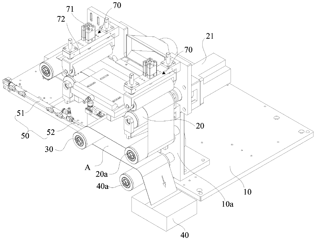
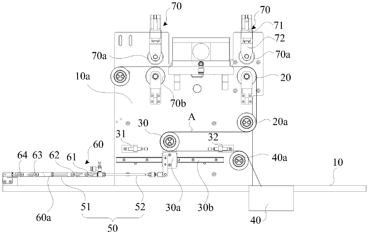
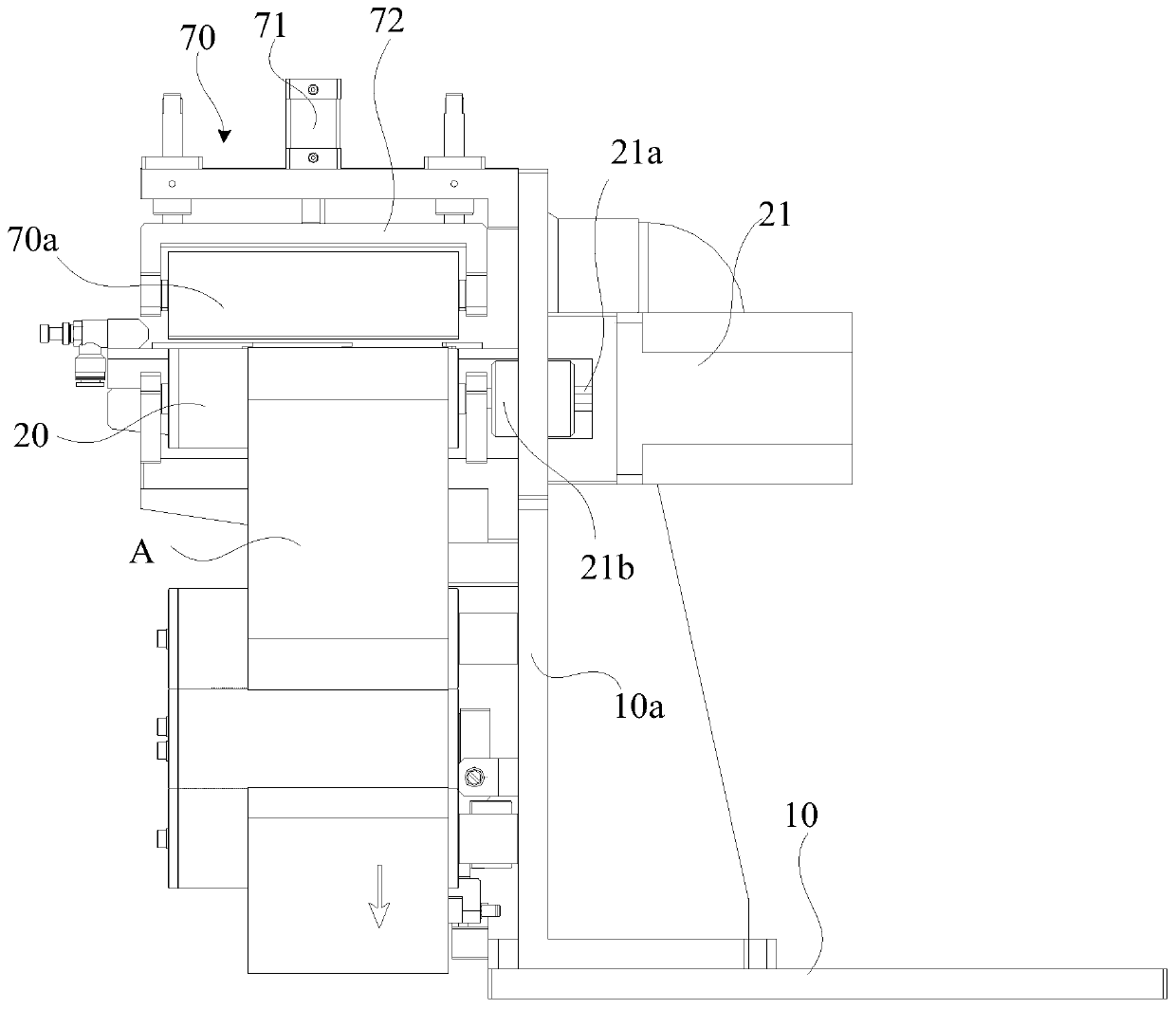
The invention relates to a material conveying device and a material conveying method. The material conveying device comprises a working table, a driving roller shaft, a driven roller shaft, a materialcollecting mechanism, a telescopic air cylinder and a controller, wherein the working table is fixedly connected with a mounting plate; the driving roller shaft is rotationally connected to the mounting plate and is used for conveying a material belt; the material belt conveyed by the driving roller shaft is connected with the mounting plate through the driven roller shaft and is connected to thematerial collecting mechanism, the driven roller shaft is connected with the mounting plate in a sliding mode through a sliding seat, and the driven roller shaft is rotationally connected with the sliding seat; and the telescopic air cylinder drives the sliding seat to slide relative to the mounting plate under the control of the controller so as to keep the tensioning material belt through the driven roller shaft. According to the material conveying device and the material conveying method, by controlling the movement of the driven roller shaft relative to the mounting plate, the tensioningforce of the driven roller shaft to the material belt is kept, so that the material belt cannot be too tight or too loose in the conveying process to influence the material belt conveying stability; and in this way, the material belt can be stably conveyed.

Description

technical field [0001] The invention belongs to the technical field of mechanical processing, and in particular relates to a feeding device and a feeding method. Background technique [0002] With the development of modern industry, flexible material roll products have higher and higher requirements for laser marking automation, but in the automatic production process, some material rolls are processed by laser processing, and the processing of material rolls is carried out in sections , during the segmental feeding process, the flexible coil material will be continuously accelerated, decelerated, and stopped. Risks such as tearing and stretching deformation will lead to unstable friction and traction force on the material roller, which will affect the stability of feeding. Contents of the invention [0003] Based on this, it is necessary to provide a conveying device and a conveying method capable of improving the stability of conveying. [0004] The invention provides ...

Claims


Application Information

Patent Timeline
Patent Type & Authority Applications(China)
IPC IPC(8): B65H23/26B65H26/00
CPCB65H23/26B65H26/00
Inventor 曹洪涛孙照飞张兴伟刘亮吕启涛高云峰
Owner HANS LASER TECH IND GRP CO LTD
Learn More