Wire joint tin hanging device for indoor decoration

A technology for wire joints and interior decoration, applied in coating, metal material coating process, hot dip plating process, etc., can solve the problems of cumbersome, difficult to spill tin liquid, etc., to achieve the effect of convenient use

Inactive Publication Date: 2019-11-05
安徽省贵安建筑安装有限公司
View PDF5 Cites 0 Cited by
  • Summary
  • Abstract
  • Description
  • Claims
  • Application Information

AI Technical Summary

Problems solved by technology

[0007] In order to overcome the cumbersome operation of hanging tin now, and the shortcoming that the operator will be scalded by accidentally spilling the tin liquid, and the depth of putting the wire connector into the cylinder is different each time, the technical problem of the present invention is to provide a This kind of tin liquid is not easy to spill when it is carried and moved, it will not burn the operator, the operation is relatively simple, and the liquid level of the tin liquid is always kept at a certain height. The wire joint hanging tin device for interior decoration

Method used


Image

  • Wire joint tin hanging device for indoor decoration
  • Wire joint tin hanging device for indoor decoration
  • Wire joint tin hanging device for indoor decoration

Examples


Embodiment 1

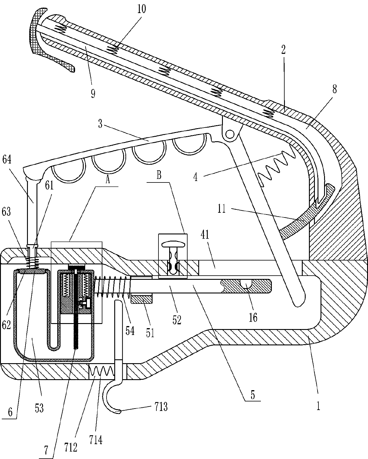
[0021] A wire connector hanger for interior decoration, such as Figure 1-2 As shown, it includes a cylinder body 1, a fixed handle 2, an L-shaped handle 3, a first spring 4, a material storage device 5 and a sealing device 6, the fixed handle 2 is installed on the top right of the cylinder body 1, and the left part of the cylinder body 1 is Open, the fixed handle 2 is equipped with an L-shaped handle 3 through a hinged connection, the first spring 4 is connected between the L-shaped handle 3 and the inner left side of the fixed handle 2, and an opening 41 is opened on the right side of the top of the cylinder 1 , the bottom of the L-shaped handle 3 passes through the opening 41 and is located in the cylinder 1, the cylinder 1 is provided with a storage device 5, wherein the storage device 5 is used to store tin liquid, and the left part of the cylinder 1 is provided with a sealing device 6, wherein the sealing device 6 is used to seal the storage device 5 .

[0022] The stor...

Embodiment 2

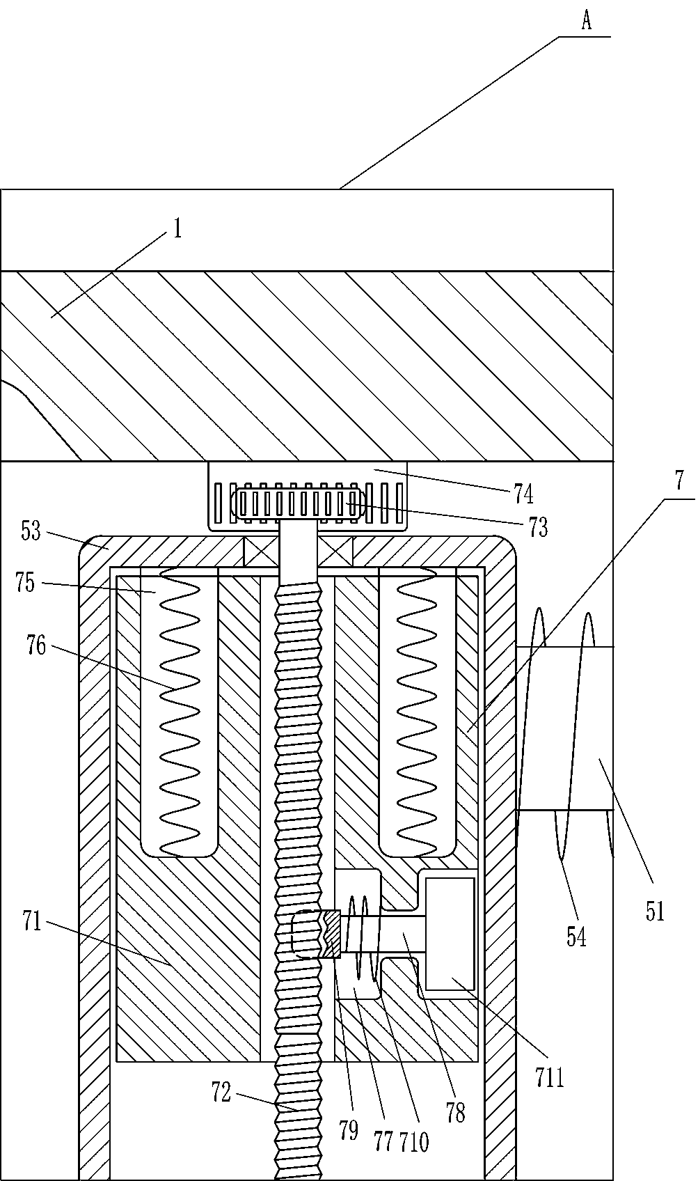
[0026] On the basis of Example 1, such as Figure 1-2Shown, also comprise limit device 7, limit device 7 comprises hollow sliding block 71, threaded rod 72, ratchet 73, tooth bar 74, the 4th spring 76, horizontal movable bar 78, half nut 79, the 5th spring 710 , fixed high-temperature magnet 711, movable high-temperature magnet 713 and the sixth spring 714, U-shaped heating cylinder 53 right side sliding type is provided with hollow sliding block 71, and U-shaped heating cylinder 53 right side upper rotating type is connected with threaded rod 72, threaded rod 72 is located in the hollow sliding block 71, a ratchet 73 is installed on the top of the threaded rod 72, a rack 74 is installed on the inner top of the left side of the cylindrical body 1, the rack 74 is engaged with the ratchet 73, and vertical holes are opened on the left and right sides of the top of the hollow sliding block 71. Straight opening 75, a fourth spring 76 is connected between the bottom of the vertical ...

Embodiment 3

[0029] On the basis of Example 2, such as Figure 1-3 Shown, also comprise special-shaped bar 9, the 7th spring 10 and the first clamp bar 11, have special-shaped opening 8 in fixed handle 2, be provided with special-shaped bar 9 movablely in special-shaped opening 8, special-shaped bar 9 tops and Seventh springs 10 are evenly spaced between the tops of the special-shaped openings 8, and the outer right side of the L-shaped handle 3 is equipped with a first clamping rod 11, which cooperates with the special-shaped rod 9.

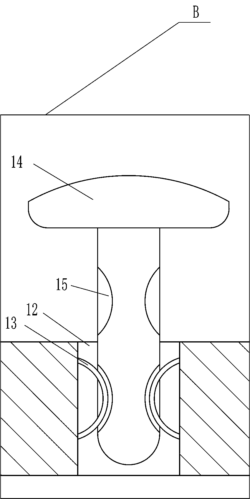
[0030] It also includes an arc-shaped reed 13 and a second clamping rod 14. There is a vertical hole 12 in the middle of the upper part of the cylinder body 1. The left and right sides of the vertical hole 12 are provided with arc-shaped reeds 13. The vertical hole 12 is slidingly provided with The second clamping rod 14 has a groove 15 matching with the arc-shaped reed 13 on the second clamping rod 14 , and a clamping hole 16 matching with the second clampi...


PUM


Abstract

The invention relates to a tin hanging device, in particular to a wire joint tin hanging device for indoor decoration. The technical problem is about how to design a wire joint tin hanging device forindoor decoration, wherein when the wire joint tin hanging device is carried to move, tin liquid is not likely to be spilled, an operator cannot be scalded, operation is simple, and the liquid level of the tin liquid is maintained at a certain height all the time. The wire joint tin hanging device for indoor decoration comprises a cylinder body, a fixed handle and the like, and the fixed handle isinstalled at the right portion of the top of the cylinder body. By means of the wire joint tin hanging device for indoor decoration, due to the L-shaped handle, a cover can be driven to move upwards,a U-shaped heating cylinder can be not covered any more, the U-shaped heating cylinder can also be driven to move out of the cylinder body, the operator can hang tin on a wire joint conveniently, dueto cooperation of a ratchet wheel and a rack, a hollow sliding block can be driven to move downwards gradually, the tin liquid level at the left portion of the U-shaped heating cylinder can be at a proper position all the time, and use of the operator can be facilitated.

Description

technical field [0001] The invention relates to a tin hanger, in particular to a tin hanger for wire joints used for interior decoration. Background technique [0002] Tin, a metallic element, is a metallic element with a silver-white luster and a low melting point. It is divalent or tetravalent in the compound and will not be oxidized by air. It mainly exists in the form of dioxide and various sulfides. [0003] During indoor decoration, wires are often routed inside the wall, and there are generally more wire connectors where switches and sockets are installed. Most of the wire connectors are multi-strand copper core wires, and multi-strand wires are composed of many thin wires. In this way, the surface area is large, and monofilament copper is relatively easy to oxidize to produce copper rust, which will affect the electrical connectivity. [0004] Therefore, it is necessary to hang tin on the joint of the wire. After the tin is hung, the wire end will be harder than bef...

Claims


Application Information

Patent Timeline
Patent Type & Authority Applications(China)
IPC IPC(8): C23C2/08C23C2/34
CPCC23C2/08C23C2/34
Inventor 夏小云
Owner 安徽省贵安建筑安装有限公司
Why Eureka
Try Eureka