
A support safety monitoring device

A safety monitoring and support technology, which is applied in the direction of measuring devices, elastic testing, force/torque/power measuring instruments, etc., can solve problems such as inaccurate monitoring results, low reliability of monitoring devices, and weak space.

Active Publication Date: 2020-11-24
GUANGZHOU URBAN PLANNING & DESIGN SURVEY RES INST
View PDF8 Cites 0 Cited by
  • Summary
  • Abstract
  • Description
  • Claims
  • Application Information

AI Technical Summary

Problems solved by technology

However, the inventor found in the process of implementing the present invention that since the support structure itself is a spatial structure, void or shear deformation may occur on multiple surfaces of the support at the same time, and due to design, construction or operation, etc. The impact of various diseases caused by the reasons on the support structure itself is not independent. Only the vertical stress state and geometric deformation state of the support are monitored. The space is not strong, which will lead to the monitored stress state of the support. The accuracy of the monitoring device is low, which leads to the low accuracy of the safety monitoring of the bearing. At the same time, due to the environmental conditions of the bridge, the monitoring device is easily damaged by the environment, which affects the reliability of the monitoring device. The existing monitoring The reliability of the device itself was not verified during the monitoring of the device, so the hidden dangers of the reliability of the monitoring device could not be discovered in time, resulting in the problem that the reliability of the monitoring device was low and the monitoring results were inaccurate, which led to the failure of the safety monitoring of the support. less accurate

Method used


Image

  • A support safety monitoring device
  • A support safety monitoring device
  • A support safety monitoring device

Examples


Embodiment Construction

[0053] The following will clearly and completely describe the technical solutions in the embodiments of the present invention with reference to the accompanying drawings in the embodiments of the present invention. Obviously, the described embodiments are only some, not all, embodiments of the present invention. Based on the embodiments of the present invention, all other embodiments obtained by persons of ordinary skill in the art without creative efforts fall within the protection scope of the present invention.

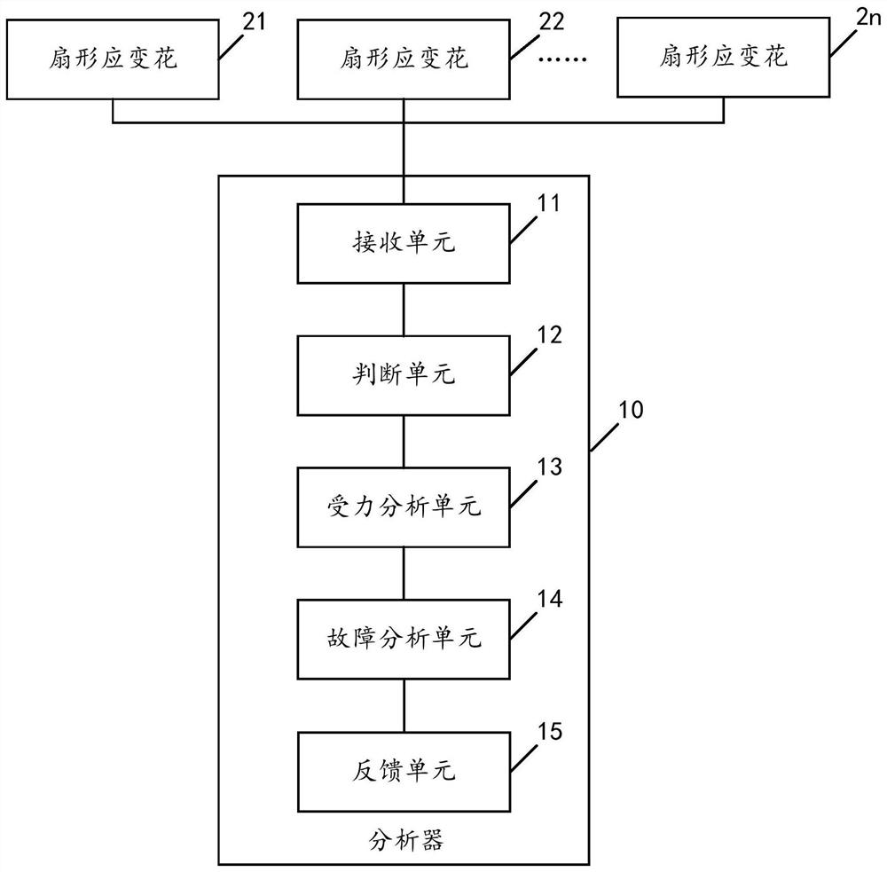
[0054] see figure 1 , is a structural schematic diagram of the support safety monitoring device in the embodiment of the present invention.

[0055] An embodiment of the present invention provides a support safety monitoring device, including an analyzer 10 and several sector rosettes 21, 22...2n; wherein each sector rosette is correspondingly pasted on each side of the support to be tested.

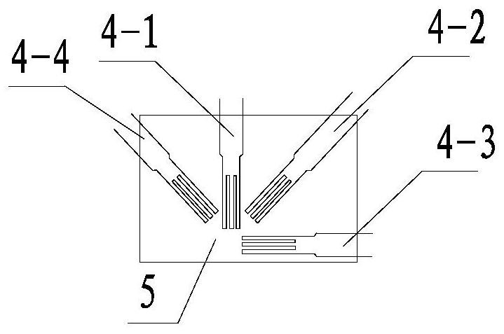
[0056] see figure 2 , each sector rosette includes a strain gauge 4-1...


PUM


Abstract

The invention discloses a support safety monitoring device. The device comprises an analyzer and a plurality of sector-shaped strain flowery parts; a receiving unit of the analyzer receives strain data, obtained from measurement by the sector-shaped strain flowery parts, of each side face of the support; a judging unit of the analyzer judges whether or not the strain data of each side face meets preset conditions; when a stress analysis unit of the analyzer judges that the strain data of each side face meets the preset conditions, the main compressive stress and main tensile stress of each side face are calculated according to the strain data of each side face, and the stress state of the support is determined and sent to a feedback unit of the analyzer for feedback to a user; a fault analysis unit of the analyzer calculates the shear stress of a side opposite to one side face when it is judged that the strain data of the side face does not meet the preset conditions, and a fault result of a strain gauge of the side face is determined and sent to the feedback unit for feedback to the user. The device can improve the accuracy of safety monitoring of the support.

Description

technical field [0001] The invention relates to the technical field of bridge engineering, in particular to a support safety monitoring device. Background technique [0002] Bearings are one of the important components of bridges. At present, bridges in my country usually use plate rubber bearings. In recent years, the society has paid more and more attention to the safety of bridges, and bearings are the force-transmitting components of the upper and lower structures of bridges. The safety of bearings is closely related to the safety of bridges. Therefore, it is of great practical significance to monitor the safety of bearings. [0003] At present, the safety monitoring of the support is generally realized by monitoring the vertical stress state and geometric deformation state of the support. However, the inventor found in the process of implementing the present invention that since the support structure itself is a spatial structure, void or shear deformation may occur on...

Claims


Application Information

Patent Timeline
Patent Type & Authority Patents(China)
IPC IPC(8): G01M5/00G01L5/00
CPCG01L5/00G01M5/0041
Inventor 裴浩楠刘春峥徐家慧
Owner GUANGZHOU URBAN PLANNING & DESIGN SURVEY RES INST
Learn More