Supercharge Your Innovation With Domain-Expert AI Agents!

Battery charging circuit

A battery charging and circuit technology, applied in the electronic field, can solve problems such as insecurity, complex structure, and high cost

Inactive Publication Date: 2019-11-05
杭州展虹科技有限公司
View PDF0 Cites 0 Cited by
  • Summary
  • Abstract
  • Description
  • Claims
  • Application Information

AI Technical Summary

Problems solved by technology

[0002] The stability of the charging current directly affects the safety of the battery. In the prior art, the design of the charging current mostly adopts the switching power supply method, which has a complex structure and high cost. At the same time, it also increases unsafe factors. A battery charging circuit is designed for this purpose.

Method used


Image

  • Battery charging circuit

Examples


Embodiment Construction

[0008] The content of the present invention will be further described below in conjunction with the accompanying drawings.

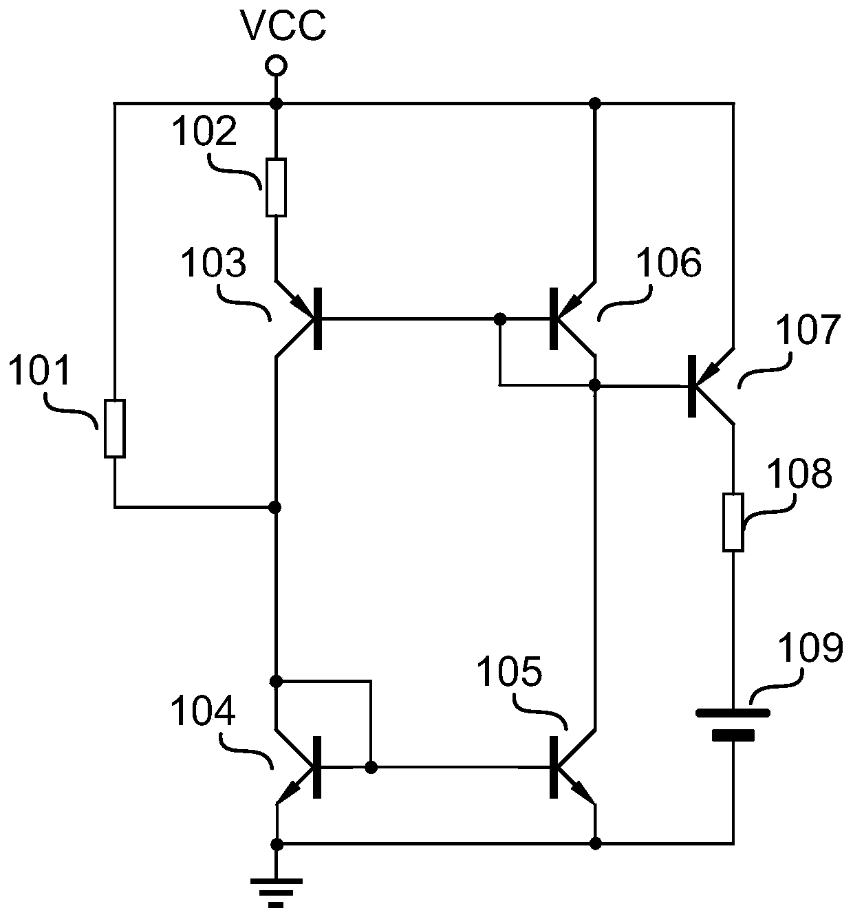
[0009] A battery charging circuit such as figure 1 As shown, it includes a first resistor 101, a second resistor 102, a first PNP tube 103, a first NPN tube 104, a second NPN tube 105, a second PNP tube 106, a third PNP tube 107, a third resistor 108 and a battery 109:

[0010] One end of the first resistor 101 is connected to the power supply voltage VCC, and the other end is connected to the collector of the first PNP transistor 103, the base and collector of the first NPN transistor 104, and the base of the second NPN transistor 105. pole; one end of the second resistor 102 is connected to the power supply voltage VCC, and the other end is connected to the emitter of the first PNP transistor 103; the base of the first PNP transistor 103 is connected to the base of the second PNP transistor 106 And the collector and the collector of the second NPN tr...


PUM


Abstract

The present invention discloses a battery charging circuit. The battery charging circuit comprises a first resistor, a second resistor, a first PNP transistor, a first NPN transistor, a second NPN transistor, a second PNP transistor, a third PNP transistor, a third resistor, and a battery. The battery charging circuit provided by the present invention can be used to improve stability for battery charging.

Description

technical field [0001] The invention relates to the field of electronic technology, in particular to a battery charging circuit. Background technique [0002] The stability of the charging current directly affects the safety of the battery. In the prior art, the design of the charging current mostly adopts the switching power supply mode, which has a complex structure and high cost, and also increases unsafe factors. Therefore, a battery charging circuit is designed. Contents of the invention [0003] The invention aims to solve the deficiencies of the prior art, and provides a battery charging circuit. [0004] A battery charging circuit, comprising a first resistor, a second resistor, a first PNP tube, a first NPN tube, a second NPN tube, a second PNP tube, a third PNP tube, a third resistor and a battery: [0005] One end of the first resistor is connected to the power supply voltage VCC, and the other end is connected to the collector of the first PNP transistor and t...

Claims


Application Information

Patent Timeline
Patent Type & Authority Applications(China)
IPC IPC(8): H02J7/00
CPCH02J7/0029
Inventor 孙殷
Owner 杭州展虹科技有限公司
Features
  • R&D
  • Intellectual Property
  • Life Sciences
  • Materials
  • Tech Scout
  • Unparalleled Data Quality
  • Higher Quality Content
  • 60% Fewer Hallucinations
Learn More