Direct-current distribution electronic soft start switch

A soft start switch, electronic technology, applied in DC network circuit devices, emergency protection circuit devices for limiting overcurrent/overvoltage, electrical components, etc., can solve problems that are prone to failure, expensive, and unable to achieve soft switching question

Active Publication Date: 2020-08-25
SHANGHAI HONYO ELECTRIC CO LTD
View PDF9 Cites 3 Cited by
  • Summary
  • Abstract
  • Description
  • Claims
  • Application Information

AI Technical Summary

Problems solved by technology

[0005] 1. Soft switching cannot be achieved at the moment of switching;
[0006] 2. It is necessary to set TVS (transient diode) to suppress the overvoltage. The life of TVS is extremely limited, it is easy to fail, and it is expensive

Method used


Image

  • Direct-current distribution electronic soft start switch
  • Direct-current distribution electronic soft start switch
  • Direct-current distribution electronic soft start switch

Examples


Embodiment Construction

[0051] The present invention will be further described below in conjunction with the accompanying drawings.

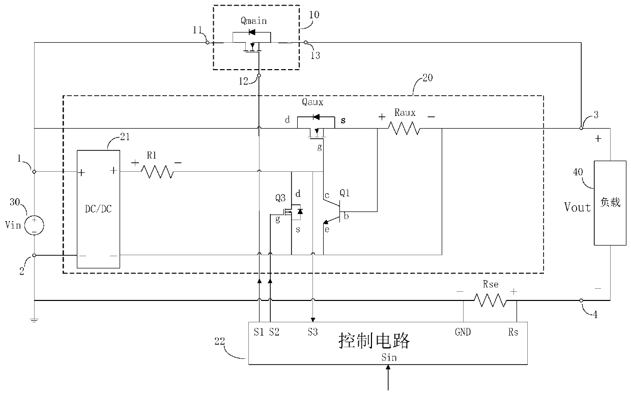
[0052] Such as figure 1 As shown, the DC power distribution electronic soft-start switch of this embodiment includes: a main switch circuit 10, an auxiliary switch circuit 20, and first, second, third and fourth common terminals 1, 2, 3, and 4;

[0053] The main switch circuit 10 includes a power terminal 11, a signal terminal 12 and a load terminal 13, the power terminal 11 is connected to the first common terminal 1, and the load terminal 13 is connected to the third common terminal 3, so The signal terminal 12 is used for receiving control signals. A DC power supply 30 is connected between the first and second common terminals 1 and 2, and a load 40 is connected between the third and fourth common terminals 3 and 4, and the control signal received by the signal terminal 12 executes the main Opening / closing of the switching circuit 10;

[0054] The auxiliary switc...


PUM


Abstract

The invention discloses a direct-current distribution electronic soft start switch which comprises a main switch circuit, an auxiliary switch circuit, a first common end, a second common end, a thirdcommon end and a fourth common end. The main switch circuit comprises a power supply terminal, a signal terminal and a load terminal which are respectively connected with the first common end and thethird common end; the auxiliary switch circuit comprises a current limiting circuit composed of a semiconductor switch Qaux, a resistor Raux, a resistor R1 and a triode Q1, a buffer circuit composed of an inductor L1, a diode D1 and a capacitor C1, a timing turn-off circuit composed of a semiconductor switch Q3, a triode Q2, a resistor Rt and a capacitor Ct, a direct-current power supply module and a control circuit. The electronic soft start switch realizes soft start, safe turn-off and stable switching of fault current, is good in reliability, and is longer in service life and lower in costcompared with a mode of suppressing overvoltage by using a TVS device.

Description

technical field [0001] The invention belongs to the field of DC power distribution switches, in particular to a DC power distribution electronic soft start switch. Background technique [0002] In a DC system, there are large capacitances on both the power supply side and the load side. At the moment when the switch is closed, the charging and discharging process of the capacitor will cause a very large inrush current, which is different from the AC system. The peak value of the inrush current often far exceeds the rated value of the switching element, seriously affecting the service life of the switching element, resulting in a high failure rate. In addition, unlike the AC system, the DC system does not have a periodic zero-crossing point, which makes it difficult to extinguish the arc when the switch is turned off, resulting in a more complicated switch design for the DC system, reduced stability and reliability, and higher costs. [0003] The switches of the existing DC...

Claims


Application Information

Patent Timeline
Patent Type & Authority Applications(China)
IPC IPC(8): H02J1/00H02H9/02H02H9/04
CPCH02J1/00H02H9/02H02H9/025H02H9/045Y02B70/10
Inventor 叶阳
Owner SHANGHAI HONYO ELECTRIC CO LTD
Why Eureka
Try Eureka