Adjustable storage battery testing instrument

A tester and storage battery technology, which is applied in the direction of instruments, measuring electricity, measuring devices, etc., can solve the problems of inconvenient portability, unstable discharge current, and inability to control, etc., and achieve the effects of easy portability, reduced volume, and stable operation

Active Publication Date: 2010-01-13
SHANGHAI POWER STATION
View PDF0 Cites 2 Cited by
  • Summary
  • Abstract
  • Description
  • Claims
  • Application Information

AI Technical Summary

Problems solved by technology

However, for this adjustable current discharge model, there are several disadvantages: 1. There are blind spots in the measurement range. When the measurement range is below 10%, about 50A, the discharge current becomes unstable and cannot be controlled; when it is below 20 , the discharge current cannot be adjusted at all.
2. Since the accuracy is fixed, a large range determines a large error, and the current of the small scale difference cannot be adjusted, that is to say, it is impossible to achieve fine adjustment in a small range. The adjustable accuracy of most products is 5-10A
3. Large size, not easy to carry
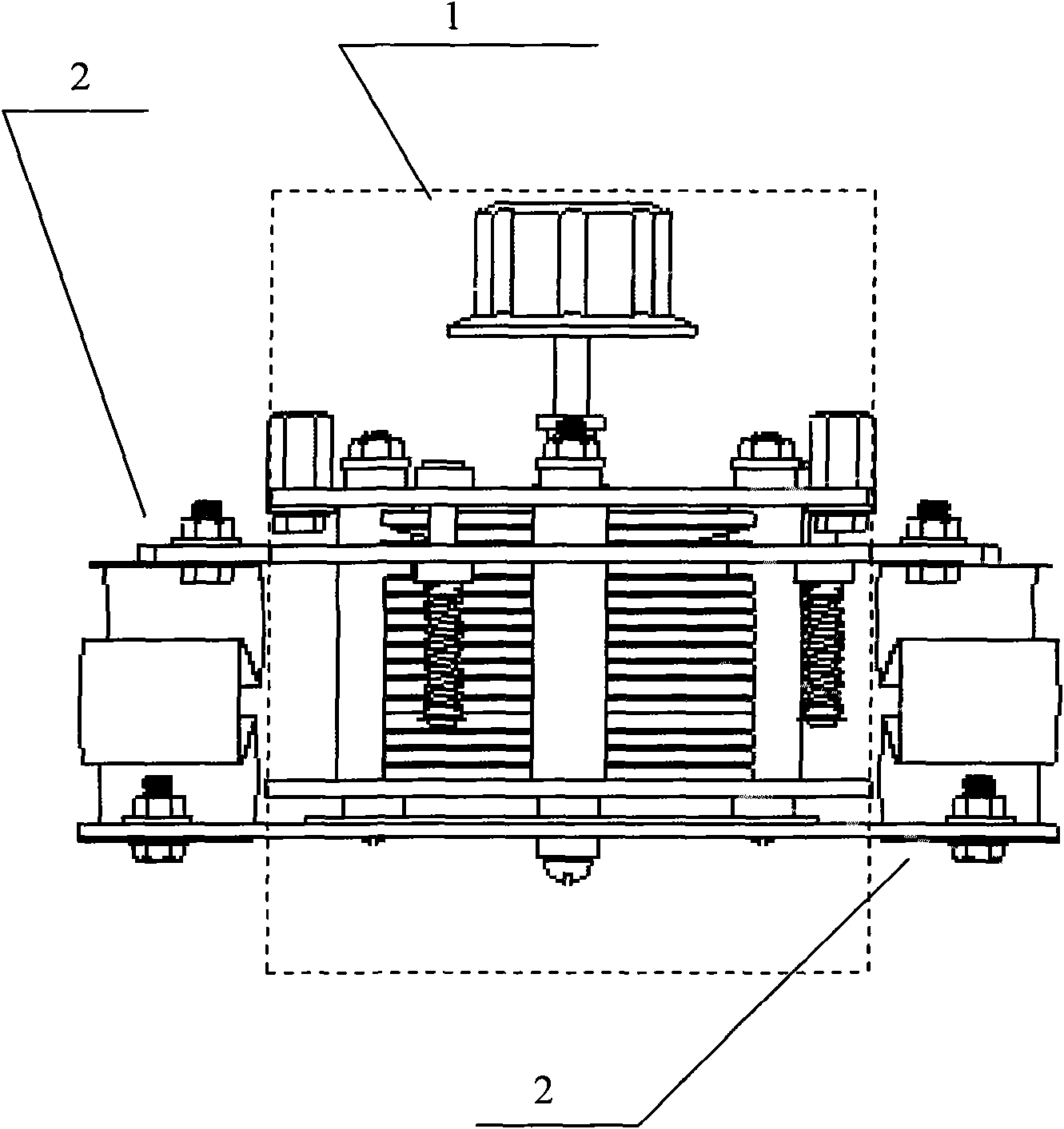
In the prior art, the structure of a sliding rheostat using a graphite stack is as follows figure 1 As shown, it includes the graphite stack structure (1) and the current limiting devices (2) on both sides; the working principle of the graphite stack is to pile up multiple graphite sheets and apply pressure to it, and its ti...

Method used


Image

  • Adjustable storage battery testing instrument
  • Adjustable storage battery testing instrument
  • Adjustable storage battery testing instrument

Examples


Embodiment approach

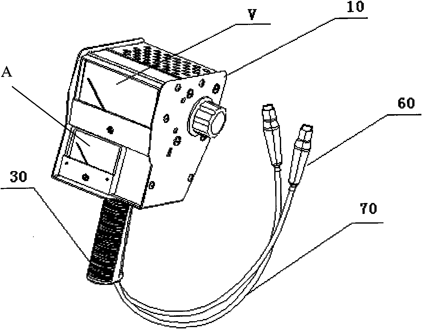
[0028] Such as figure 2 As shown, the adjustable battery tester includes an instrument housing 10, a test circuit 20 disposed inside the instrument housing, a voltmeter case disposed on the surface of the instrument housing, and a hand-held operating handle 30 disposed at the lower end of the instrument housing And the wire 70 extending from the instrument housing through the hand-held operating handle, and the test clip 60 at the end of the wire 70; the test clip 60 is a small spring clip matched with a small battery.

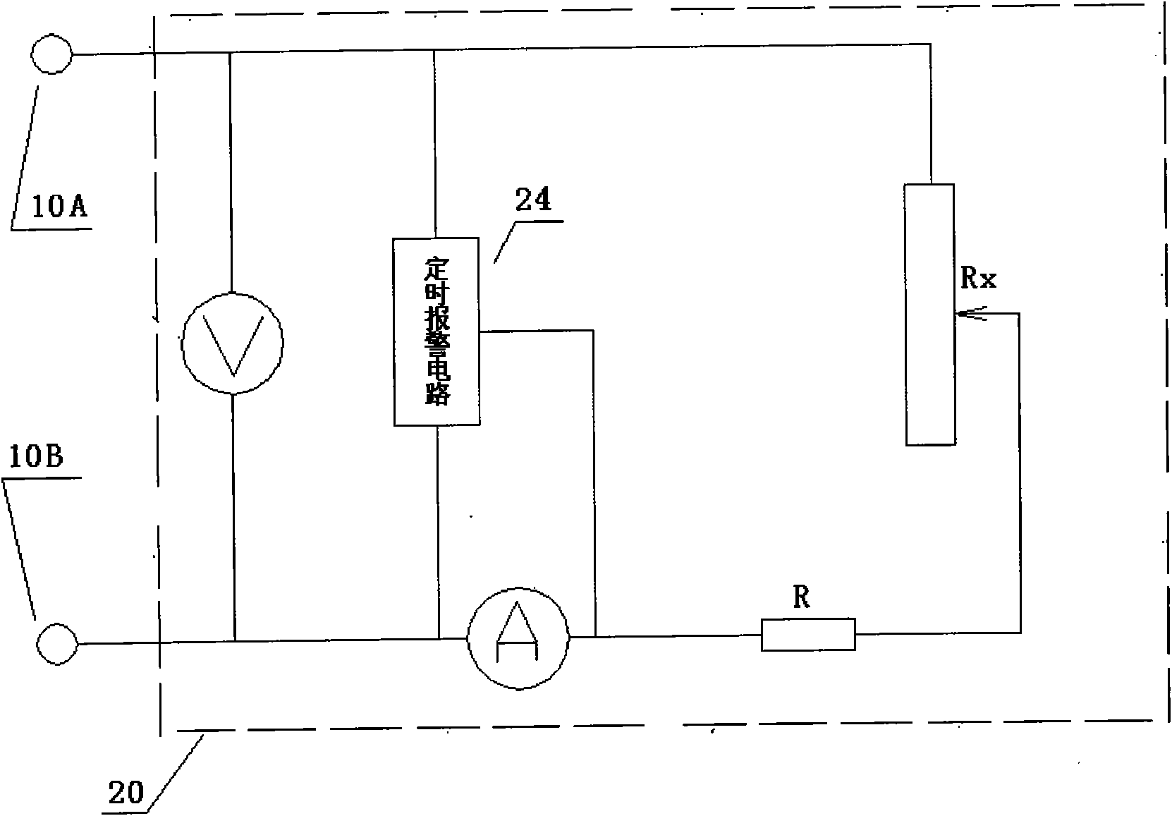
[0029] Such as image 3 As shown, the test circuit 20 of the adjustable battery tester includes a sliding rheostat Rx, a high-power resistor R, and an ammeter A connected in series between the first test terminal 10A and the second test terminal 10B in sequence, and connected in parallel to the first test terminal 10A. and a voltmeter V on the second test terminal 10B.

[0030] In this embodiment, the resistance value of the high-power resistor R is set at ...


PUM

PropertyMeasurementUnit
Resistanceaaaaaaaaaa

Abstract

The invention provides an adjustable storage battery tester, comprising an instrument shell, a test circuit arranged in the interior of the instrument shell and a voltmeter arranged on the surface of the instrument shell, wherein the voltmeter circuit is connected with the test circuit; wherein the test circuit comprises a slide rheostat and an amperemeter which are sequentially connected between a first test terminal and a second test terminal in series and a voltmeter which is connected between the first test terminal and the second test terminal in parallel and also comprises a high power resistance R; the high power resistance R, the slide rheostat Rx and the amperemeter are connected in series; and discharge current can be changed by adjusting the resistance of the high power resistance R. The invention can meet the test discharge current requirement of storage batteries discharge current of which range from 5-50A and fills the gap of market; and the invention has the advantages that adjustment precise is high, volume is small, measuring ranges are multiple, and the instrument is convenient to carry. The invention has popularization advantage especially in automobile and help-move-vehicle fields.

Description

technical field [0001] The invention relates to a battery tester, in particular to an adjustable battery tester. Background technique [0002] Among the high-current discharge battery testers on the market, there are two types: fixed resistance discharge and adjustable current discharge. In the fixed resistance discharge type, an error occurs due to a voltage drop during battery measurement, which leads to a decrease in the discharge current, and the accuracy is low, and the discharge current is low, and the measured battery range is small. The adjustable current discharge type battery tester can adjust the size of the discharge current at any time according to the capacity of the battery. The measurement result has high precision, and the discharge current is large and the measurement range is large. However, for this adjustable current discharge model, there are several disadvantages: 1. There are blind spots in the measurement range. When the measurement range is below 1...

Claims


Application Information

Patent Timeline
IPC IPC(8): G01R31/36
Inventor 范晔平姜志良李科张忠仁段领
Owner SHANGHAI POWER STATION
Why Eureka
Try Eureka