
Bearing ring grinding workshop detection line

A bearing ring and detection line technology, which is applied in the field of detection line in the grinding workshop of bearing rings, can solve problems affecting the accuracy of detection, waste of time and space, and classification of out-of-tolerance products that cannot be processed, so as to improve production efficiency and quality , improve accuracy, and improve production efficiency

Pending Publication Date: 2019-11-08
临清市万达轴承有限公司
View PDF0 Cites 0 Cited by
  • Summary
  • Abstract
  • Description
  • Claims
  • Application Information

AI Technical Summary

Problems solved by technology

[0003] In the case of the existing manual inspection technology for bearing rings, the inspection cannot be well integrated into the production process
Mainly manifested in the following aspects: (1) 100% inspection cannot be realized on the production line; (2) The inspection results of the bearing cannot be communicated with the grinding process in real time; (3) The detection environment and the production environment are quite different, which affects the accuracy of the inspection. (4) It is impossible to classify the processing out-of-tolerance products in time; (5) It cannot be connected with the follow-up process of bearing production, which causes waste in terms of time and space, and is easy to bring extra work to the bearing ring (such as Anti-rust) and accidental damage (such as bump damage) and then lead to new quality problems

Method used


Image

  • Bearing ring grinding workshop detection line
  • Bearing ring grinding workshop detection line
  • Bearing ring grinding workshop detection line

Examples


Embodiment Construction

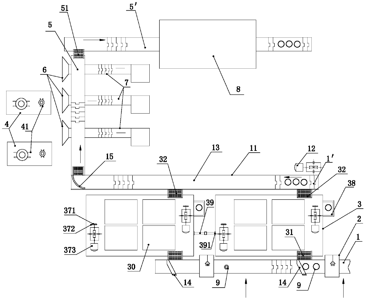
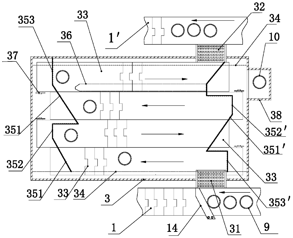
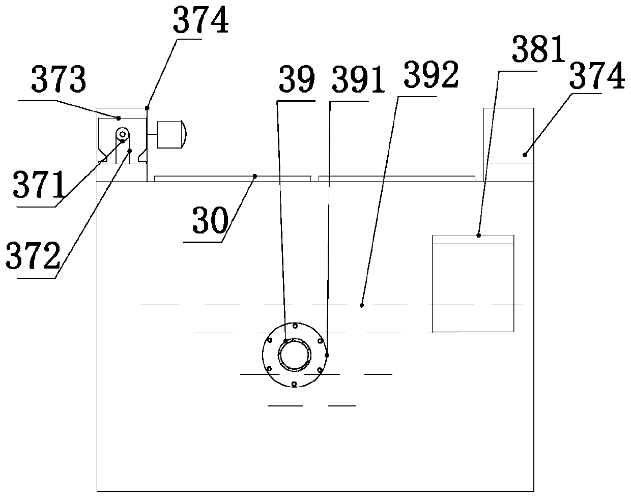
[0025] Such as Figure 1 to Figure 4 As shown, the present invention mainly includes a feed conveyor 1, a discharge conveyor 1', a spray box 2, an isothermal box 3, a detection table 4, a detection conveyor 5, a return conveyor 5', a classification tank 6, a classification Platform 7 and washing machine 8, the present invention will be described in detail below in conjunction with accompanying drawing.

[0026] Such as figure 1 As shown, the feeding conveyor 1 is arranged horizontally, and the feeding conveyor includes a supporting frame 11, a flexible belt 13 arranged on the supporting frame, a transmission roller matched with the flexible belt, and a transmission motor 12 for driving the transmission roller to rotate. , two distribution plates 14 arranged left and right are arranged above the feeding conveyor, the distribution plates are fixedly connected with the carrier frame, and the two distribution plates are rectangular plates and arranged in parallel. Two spray boxe...


PUM


Abstract

The invention provides a bearing ring grinding workshop detection line. The bearing ring grinding workshop detection line is used for achieving automated detection of bearing rings. The bearing ring grinding workshop detection line comprises a feeding conveyor, a discharging conveyor, an isothermal box, a detection conveyor, a detection table, a classifying table, a classifying groove and a returnconveyor. Two left-right arranged spraying boxes are arranged on the feeding conveyor. The discharging conveyor and the feeding conveyor are arranged in parallel. The isothermal box is located between the feeding conveyor and the discharging conveyor, a feeding ramp is arranged between the isothermal box and the feeding conveyor, a discharging ramp is arranged between the isothermal box and the discharging conveyor, and a transferring unit for driving an inner ring or an outer ring to enter and exit the isothermal box is arranged in the isothermal box. The detection conveyor is arranged in amanner that the detection conveyor is perpendicular to the discharging conveyor. The detection table is arranged on the left side of the detection conveyor, and a detector is arranged on the detectiontable. The classifying groove is formed in the detection conveyor, and the lower end of the classifying groove is engaged with a classifying table. The return conveyor is arranged in a manner that the return conveyor is perpendicular to the detection conveyor. By means of the bearing ring grinding workshop detection line, automated detection of bearing rings can be achieved.

Description

technical field [0001] The invention relates to the technical field of bearing ring detection, in particular to a detection line for a bearing ring grinding workshop used in a bearing ring grinding workshop and matched with a grinding processing line. Background technique [0002] Bearing is a very important part in the machinery industry. It is widely used and has a wide variety. The processing accuracy and quality of bearings are related to the performance, quality and life of mechanical products. Therefore, the processing quality inspection of various bearings has always been Manufacturers are concerned about issues that matter. In the high-level bearing grinding process, online intelligent detection has been realized, but the detection methods of quite a few bearing manufacturers in China are still in the stage of combining semi-automatic and manual, and the establishment of a convenient, feasible and reliable detection line is still There is a big market. [0003] In ...

Claims


Application Information

Patent Timeline
Patent Type & Authority Applications(China)
IPC IPC(8): B07C5/00B07C5/02B07C5/36
CPCB07C5/00B07C5/02B07C5/362
Inventor 汪姝含汪文政曹培斌路新庆蒋义志蒋克飞汪文博田民
Owner 临清市万达轴承有限公司
Learn More