
Forced demolding device used after injection mold product forming

A technology of forced demoulding and injection molds, which is applied in the field of injection molds, can solve the problems of low demoulding efficiency, easy deformation, scalded parts, etc., and achieve the effect of reducing scald incidents and high demoulding efficiency

Active Publication Date: 2019-11-08
南通思泽塑业有限公司
View PDF4 Cites 9 Cited by
  • Summary
  • Abstract
  • Description
  • Claims
  • Application Information

AI Technical Summary

Problems solved by technology

[0005] Aiming at the deficiencies of the prior art, the present invention provides a forced demoulding device after the injection mold product is formed, which has the advantages of high demoulding efficiency, avoiding burns and not easy to deform, and solves the problem of traditional demoulding mechanism when demoulding. Low efficiency, manual demoulding is required, which may easily cause burns and easy deformation of parts

Method used


Image

  • Forced demolding device used after injection mold product forming
  • Forced demolding device used after injection mold product forming
  • Forced demolding device used after injection mold product forming

Examples


Embodiment Construction

[0024] The technical solutions in the embodiments of the present invention will be clearly and completely described below with reference to the accompanying drawings in the embodiments of the present invention. Obviously, the described embodiments are only a part of the embodiments of the present invention, not all of the embodiments. The embodiments of the present invention, and all other embodiments obtained by those of ordinary skill in the art without creative work, fall within the protection scope of the present invention.

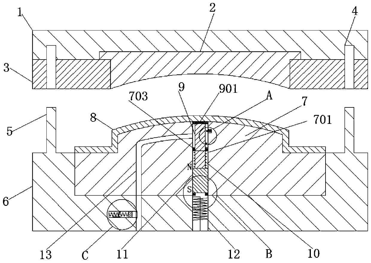
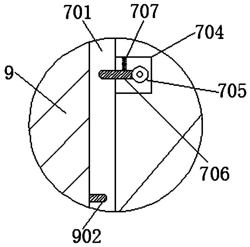
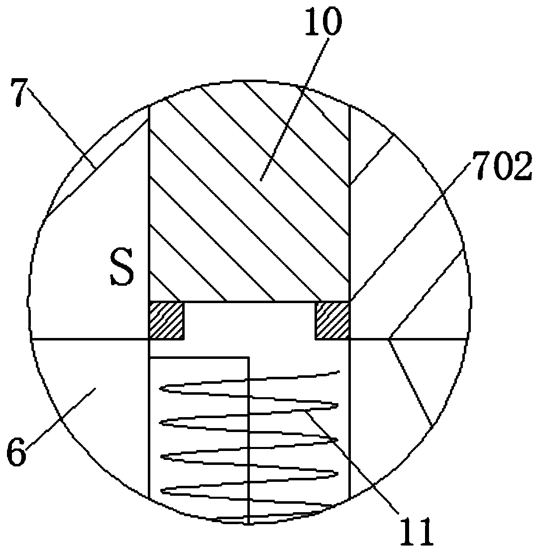
[0025] see Figure 1-4 , an injection mold product forced demoulding device after molding, including a fixed mold base 1, a fixed template 2 is fixedly connected directly below the fixed mold base 1, and a side surface of the fixed template 2 is installed under the fixed mold base 1. Fixed connection with The fixed plate 3, the inner two sides of the fixed die base 1 and the fixed plate 3 are fixedly installed with a guide sleeve 4, and a guide post 5...


PUM


Abstract

The invention relates to the technical field of injection molds, and discloses a forced demolding device used after injection mold product forming. The forced demolding device comprises a fixed mold holder, the inner middle of a mold core is connected with a sliding column, the outer side of the lower end of the sliding column is connected with a first spring, a permanent magnet is arranged underthe sliding column, an electromagnetic induction coil is arranged under the permanent magnet, and the interior of a movable mold holder and the interior of the mold core are connected with a gas feedpipe. A magnetic field generated by the electromagnetic induction coil drives the sliding column to vibrate a workpiece, after the workpiece is loosened, a second metal column make contact with a first metal column, gas of the gas feed pipe blows the workpiece, meanwhile air pressure pushes a sliding block to compress a second spring to drive a metal ball to slide on a variable resistor, the output power of an air supply device is adjusted, and large impact of stable and constant power on the workpiece is prevented. Because of the structure, not only can the workpiece be forced out of the moldcore, but also the workpiece can also be cooled, and the occurrence of scald incidents of workers is reduced.

Description

technical field [0001] The invention relates to the technical field of injection moulds, in particular to a forced demoulding device after an injection mould product is formed. Background technique [0002] Injection mold is a tool for producing plastic products, and it is also a tool for giving plastic products complete structure and precise dimensions. Injection molding injects the heated and melted plastic into the mold cavity under high pressure from the injection molding machine, and after cooling and solidifying, the molded product is obtained. The injection mold consists of a movable mold and a fixed mold. The movable mold is installed on the moving template of the injection molding machine, and the fixed mold is installed on the fixed template of the injection molding machine. During injection molding, the movable mold and the fixed mold are closed to form a gating system and Cavity, when the mold is opened, the movable mold and the fixed mold are separated to take ...

Claims


Application Information

Patent Timeline
Patent Type & Authority Applications(China)
IPC IPC(8): B29C45/40B29C45/43
CPCB29C45/40B29C45/43
Inventor 李素燕
Owner 南通思泽塑业有限公司
Learn More