Lamp warming type bath heater

A technology of Yuba and lamp heating, which is applied in household heating, space heating and ventilation details, heating methods, etc. It can solve problems such as uneven heating, poor comfort, and small heating area, so as to improve heating uniformity and prevent The effect of discomfort

Pending Publication Date: 2019-11-08
嘉兴领创电气科技股份有限公司
0 Cites 0 Cited by

AI-Extracted Technical Summary

Problems solved by technology

Existing light-warming heaters usually have four heating bulbs, and the way to open the bulbs is to open all four bulbs or to open two bulbs on one side. There is a problem that the lower side of the heater is cold and hot at the same time, heating is uneven, and the comfort is poor.
In addition, the...

Method used

The present invention can improve the heating uniformity of the Yuba when two heating lamps are turned on by replacing the traditional unilateral two lighting methods of the heating lamp with the diagonal two lighting methods, so as to prevent the lower side of the Yuba from being cold ...

Abstract

The invention discloses a lamp warming type bath heater which comprises an outer shell, a ventilating motor, a wind wheel, an illuminating lamp and four heating lamps. The outer shell comprises a boxbody and a panel for closing an opening of the box body. The four heating lamps are distributed rectangularly and stretch out from through holes of the panel. The lighting mode of the four heating lamps is as follows: the two heating lamps located on diagonals are lighted independently or the four heating lamps are lighted simultaneously. By replacing a conventional mode of lighting the two heating lamps on the single side by a mode of lighting the two heating lamps on the diagonals, the heating uniformity of the bath heater can be improved when two heating lamps are lighted, so that discomfort as one side of the lower side of the bath heater is hot while the other side is cold is prevented. By arranging a position adjuster, a nut is driven by a position adjusting motor to move to a certain height along a lead screw, so that the ground clearances and the orientations of the heating lamps can be changed according to demands of users.

Application Domain

Technology Topic

Image

  • Lamp warming type bath heater
  • Lamp warming type bath heater
  • Lamp warming type bath heater

Examples

  • Experimental program(1)

Example Embodiment

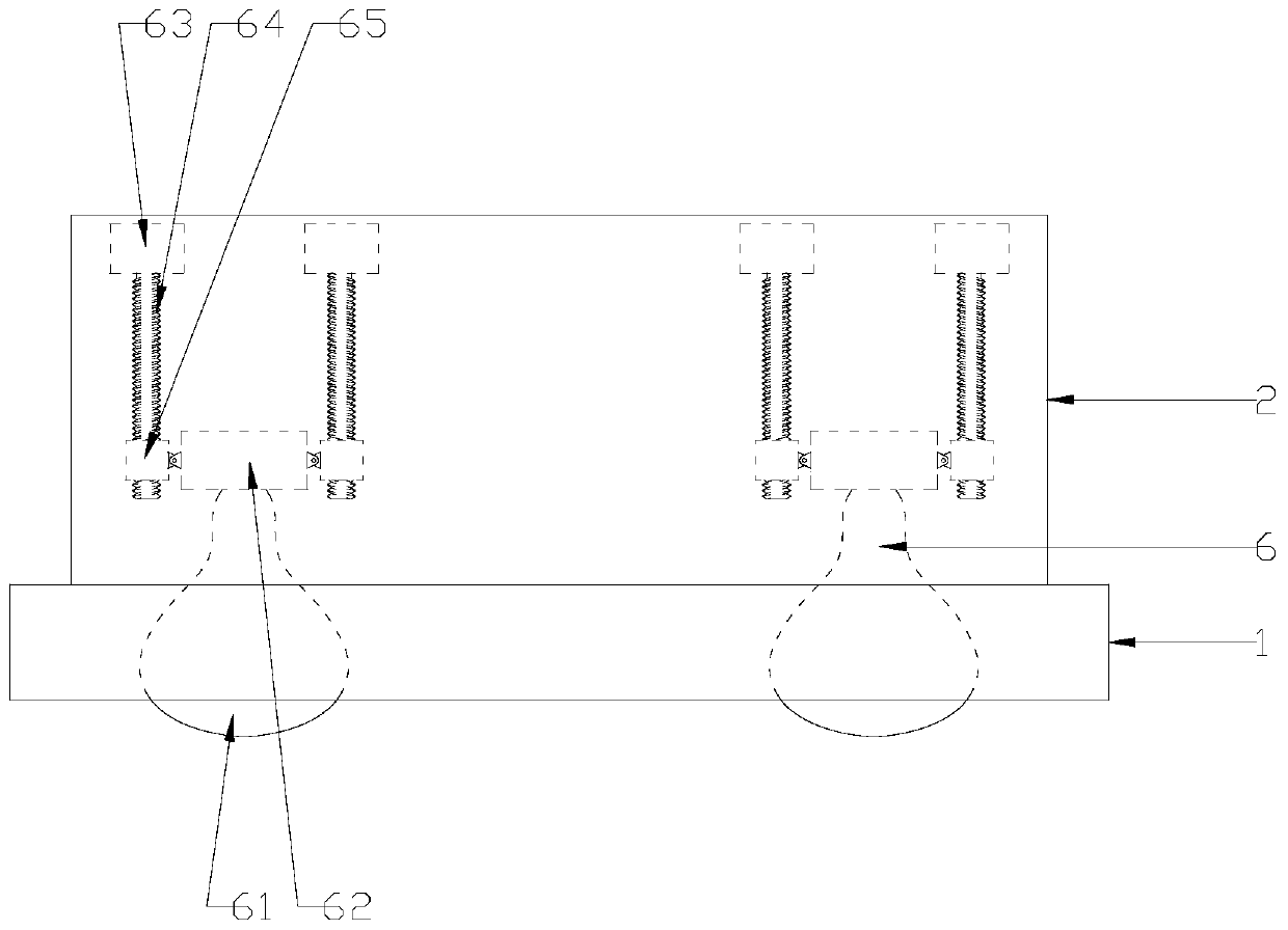
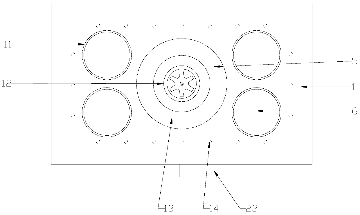
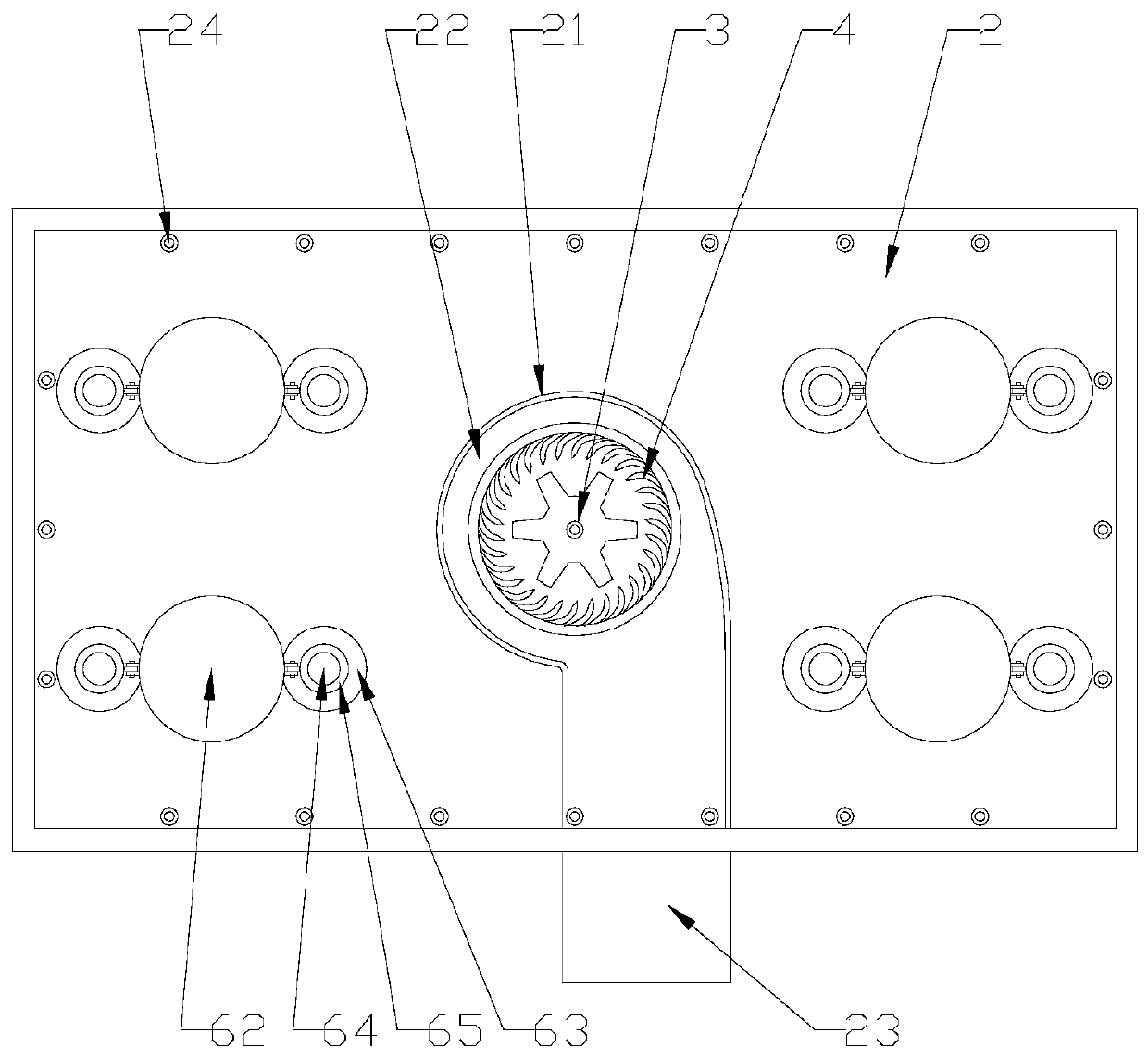
[0017] refer to figure 1 , figure 2 and image 3 , a light heating type Yuba in the present invention, comprising an outer casing, a ventilation motor 3, a wind wheel 4, a lighting lamp 5 and a heating lamp 6, the outer casing includes a box body 2 and a panel 1 closing the opening of the box body 2, four The heating lamps 6 are distributed in a rectangular shape and protrude from the through hole 11 of the panel 1. The lighting mode of the four heating lamps 6 is that two of the heating lamps 6 located on the diagonal line are lit separately or four are simultaneously lit. The inside of the box 2 is surrounded by an arc-shaped baffle 21 to form an annular air chamber 22, one side of the annular air chamber 22 communicates with the outside air, and the panel 1 is provided with an air inlet corresponding to the annular air chamber 22. The air inlet 12 is located between the four heating lamps 6, the ventilation motor 3 is arranged in the center of the annular air cavity 22, the wind wheel 4 is connected with the ventilation motor 3, and the wind wheel 4 is a centrifugal wind wheel, and the outer side of the box body 2 is provided with a ventilation pipe 23, and the ventilation pipe 23 passes through the box wall of the box body 2 to communicate with the annular wind chamber 22, and the box body 2 is provided with The lighting lamp holder, the lighting lamp 5 is fixed on the lighting lamp holder, the panel 1 is provided with a light-transmitting plate 13, the lighting lamp 5 is a ring lamp and is arranged between four heating lamps 6, the box The edge of the body 2 is provided with several card posts 24, and the panel 1 is provided with several card slots 14 corresponding to the card posts 24. When the box body 2 and the panel 1 are connected, the card posts 24 and the card slots 14 Interlocking with each other, the heating lamp 6 includes a heating bulb 61, a heating lamp holder 62 and several positioners arranged around the heating bulb 61 and the heating lamp holder 62, and the positioner includes a positioning motor 63, a screw rod 64 and screw nut 65, the heating bulb 61 is fixed on the heating lamp holder 62, the screw nut 65 is fixed on the screw rod 64 and hinged with the adjacent side of the heating lamp holder 62, the screw rod 64 is connected to the panel 1 It is vertical and driven to rotate by the position adjustment motor 63 fixed in the box body 2, and there are 2 to 4 sets of position adjusters hinged around the circumference of the heating lamp holder 62.
[0018] Working process of the present invention:
[0019] When needing illumination, light illuminating lamp 5.
[0020] When ventilation is required, the ventilation motor 3 drives the wind wheel 4 to rotate, so that air enters the annular air chamber 22 from the air inlet 12 and is discharged along the ventilation pipe 23 to realize indoor ventilation.
[0021] When the lamp needs to be warmed up, the heating lamp 6 is turned on. The lighting mode of the four heating lamps 6 can realize two lamps positioned on the diagonal line to be lit separately or four lamps to be lit simultaneously according to the needs of the user.
[0022] When the height of the heating lamp 6 needs to be changed, the positioning motor 63 drives the screw rod 64 to rotate, so that the screw nut 65 moves up and down the same distance along the screw rod 64, thereby driving the heating bulb 61 and the heating lamp holder 62 to move up and down to a suitable height .
[0023] When the angle of the heating lamp 6 needs to be changed, the positioning motor 63 drives the screw mandrel 64 to rotate, so that the screw nut 65 moves up and down different distances along the screw mandrel 64, so that the heating bulb 61 and the heating lamp holder 62 are biased towards a certain direction. incline.
[0024] The present invention replaces the traditional lighting method of two lamps on one side with two lamps on a diagonal, which can improve the heating uniformity of the Yuba when the two heating lamps are turned on, and prevent the lower side of the Yuba from being hot while being cold. Feeling uncomfortable; By setting the positioner, the positioner motor is used to drive the screw nut to move along the screw rod to a certain height, so that the distance from the ground and the direction of the heating bulb can be changed according to the needs of the user.
[0025] The above-mentioned embodiment is an illustration of the present invention, not a limitation of the present invention, and any solution after a simple transformation of the present invention belongs to the protection scope of the present invention.

PUM

no PUM

Description & Claims & Application Information

We can also present the details of the Description, Claims and Application information to help users get a comprehensive understanding of the technical details of the patent, such as background art, summary of invention, brief description of drawings, description of embodiments, and other original content. On the other hand, users can also determine the specific scope of protection of the technology through the list of claims; as well as understand the changes in the life cycle of the technology with the presentation of the patent timeline. Login to view more.

Similar technology patents

Butanediol low-temperature water removal device and use method thereof

ActiveCN109966769AImprove heating uniformityImprove mixing efficiency and effectOrganic chemistryVacuum distillation separationCheck valveEngineering
Owner:ANQING HE XING CHEM

Classification and recommendation of technical efficacy words

  • Avoid discomfort
  • Improve heating uniformity

Shaving Razors and Cartridges

ActiveUS20100083510A1Avoid discomfortImprove rinsing characteristicMetal working apparatusEngineeringKnife blades
Owner:THE GILLETTE CO

Eye nursing apparatus

Owner:NINGBO YOUSHIJIA VISION CARE

Brazing machine for electric heating composite pan bottom

InactiveCN101559508AGuaranteed brazing temperatureImprove heating uniformityHeating appliancesInduction heating controlPower controlElectric heating
Owner:王新田
Why Eureka
Try Eureka