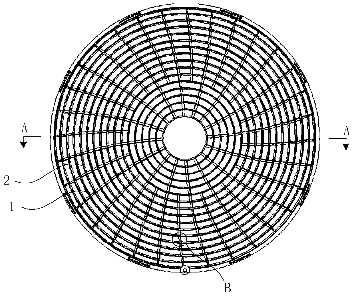
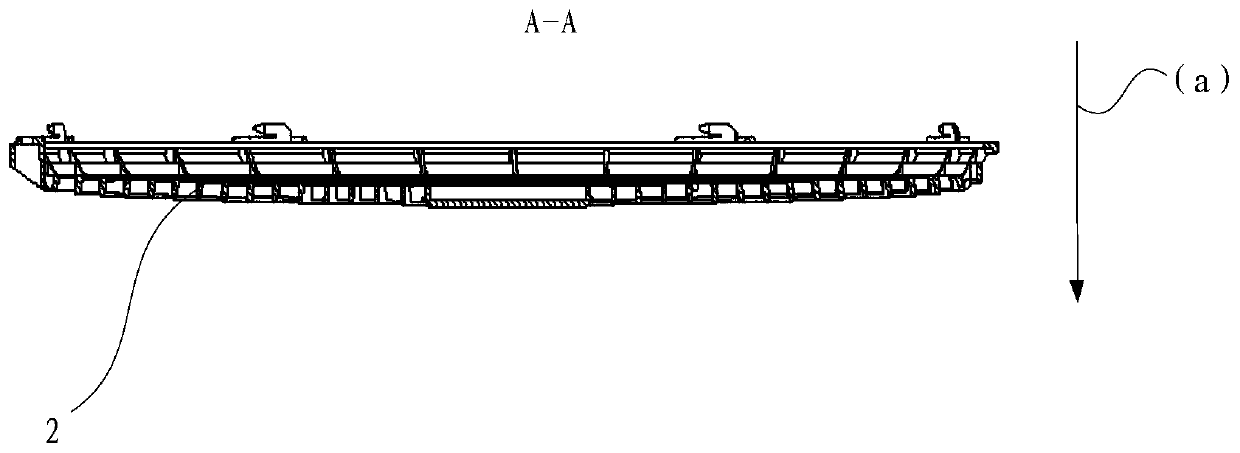
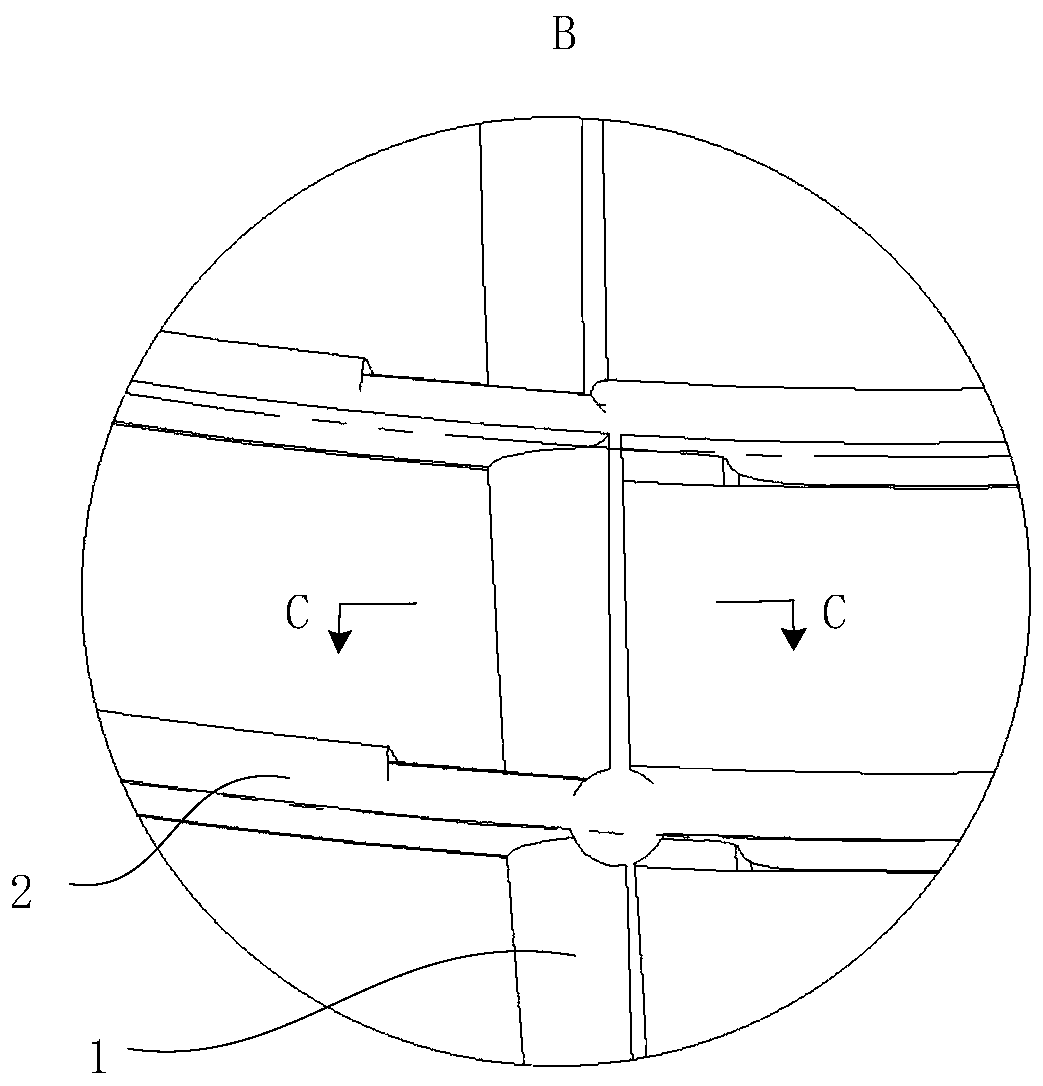
Fan cover and air conditioner

A technology of fan cover and air inlet end, which is applied in the field of air conditioning, which can solve the problems that the airflow cannot be smoothly discharged from the installation cavity and the heat exchange capacity of the air conditioner is reduced, so as to achieve the effect of reducing the contact area and improving the heat exchange capacity

Pending Publication Date: 2019-11-08
HISENSE (GUANGDONG) AIR CONDITIONER
View PDF0 Cites 0 Cited by
  • Summary
  • Abstract
  • Description
  • Claims
  • Application Information

AI Technical Summary

Problems solved by technology

[0005] The embodiment of the present invention provides a fan cover and an air conditioner. The fan cover can guide and change the flow direction of the airflow, which solves the problem that the a

Method used


Image

  • Fan cover and air conditioner
  • Fan cover and air conditioner
  • Fan cover and air conditioner

Examples


Example Embodiment

[0029] Example one

[0030] The fan cover of the embodiment of the present invention, such as Figure 4 As shown, the windward surface of the radial rib 1 along the circumferential component of the airflow is the second side surface 14, which is recessed to form a curved surface along the axial middle of the fan cover in a direction away from the center of the fan cover. Similar to the first side surface 12, the tangential direction of the air inlet end 11 of the second side surface 14 ( Figure 4 Middle, dotted line c 3 The direction shown) and the tangential direction of the air outlet 13 ( Figure 4 Middle, dotted line c 4 The direction shown) is at a certain angle, and along the axial direction of the fan cover, from the air inlet end 11 to the air outlet end 13 of the radial rib 1, the angle between the tangent direction of the second side 14 and the axial direction of the fan cover gradually Become smaller. When the airflow passes through the second side 14 of the radial ri...

Example Embodiment

[0033] Example two

[0034] The fan cover of the embodiment of the present invention, such as Figure 5 As shown, the windward surface of the radial rib 1 along the circumferential component of the airflow is the second side surface 14, and the second side surface 14 is a plane along the axial direction of the fan cover. It should be understood that "the second side surface 14 is a plane along the axial direction of the fan cover" specifically refers to, for example, Figure 5 As shown, the second side surface 14 extends along a straight line in the axial direction of the fan cover; the second side surface 14 itself has an extension along the radial direction of the fan cover and an extension along the axial direction of the fan cover. The two side surfaces 14 are flat surfaces. Compared with the first embodiment, the second side surface 14 is recessed along the axial middle of the fan cover to the leeward side of the radial rib 1 along the circumferential component of the airflo...


PUM


Abstract

The invention discloses a fan cover and an air conditioner, and relates to the technical field of the air conditioner. The fan cover can guide and change the flow direction of air flow, and solves theproblem that the air flow generated by the outdoor unit of the air conditioner cannot be smoothly discharged from an installation cavity and results in decreased heat exchange capacity of the air conditioner. The fan cover comprises a plurality of radial ribs, the radial ribs are arranged in a radial direction of the fan cover, and the radial ribs are arranged in a circumferential direction of the fan cover at internal; the air flow entering the air inlets of the radial ribs has a circumferential component rotating in the circumferential direction of the fan cover, the leeward side of the circumferential component of the radial ribs along the air flow is the first side, the first side is protruded from the circumferential component of the air flow along the radial ribs in the middle of the axial direction of the fan cover and forms a curved surface; an air conditioner comprises an outdoor unit of the air conditioner, and the outdoor unit of the air conditioner is provided with an airoutlet, and the fan cover is provided at the air outlet. The fan cover provided by the invention is used for preventing foreign matters from entering the outdoor unit of the air conditioner.

Description

technical field [0001] The invention relates to the technical field of air conditioners, in particular to a fan cover and an air conditioner. Background technique [0002] An air conditioner is a common heat exchange device, usually including an indoor unit and an outdoor unit. An axial flow fan is arranged in the outdoor unit, and the axial flow fan is used to exchange heat between the outdoor unit and the outside air. The outdoor unit is also provided with an air outlet, and the air outlet is provided with a fan cover. The fan cover is used to guide the airflow and prevent foreign matter from entering the outdoor unit through the air outlet, so as to protect the outdoor unit. The outdoor unit is usually installed on the outside of the building wall. For safety and the beauty of the wall, an installation cavity for installing the outdoor unit is usually provided on the outer wall of the wall, and grilles are arranged around the installation cavity to guide the air flow. W...

Claims


Application Information

Patent Timeline
IPC IPC(8): F24F1/06F24F1/38F24F1/48
CPCF24F1/06F24F1/38F24F1/48
Inventor 王伟戈梁勇华
Owner HISENSE (GUANGDONG) AIR CONDITIONER
Why Eureka
Try Eureka