Eureka AIR delivers breakthrough ideas for toughest innovation challenges, trusted by R&D personnel around the world.

Conical dryer for treating waste resins with radioactivity

A waste resin and radioactive technology, applied in the field of radioactive waste treatment equipment, can solve the problems of non-compliance with the principle of minimization of nuclear power waste treatment, waste price increase and large capacity increase, radioactive pollution, etc.

Inactive Publication Date: 2019-11-08
JIANGSU ZHONGHAI HUA HE ENVIRONMENTAL PROTECTION CO LTD
View PDF15 Cites 3 Cited by
  • Summary
  • Abstract
  • Description
  • Claims
  • Application Information

AI Technical Summary

Problems solved by technology

With the development of the atomic energy industry and the widespread use of radioactive isotopes, radioactive waste is increasing day by day. If it is discharged without treatment or improper treatment, the environment will be polluted by radioactivity, which will not only affect the growth of animals and plants, deteriorate water bodies, and endanger human health. even have adverse effects on future generations
[0003] Under the circumstance that the treatment and disposal of radioactive waste is becoming more and more prominent, the traditional waste resin cement solidification process technology will greatly increase the final waste price and increase the capacity, which does not meet the minimization principle of nuclear power waste treatment. At present, Germany, France, the United States and other countries have already A radioactive waste drying device has been developed and has been applied in some nuclear power plants. In addition, according to the retrieval, Chinese patent CN 103453739B discloses a waste resin drying device and drying method, but the device does not have the ability to continuously process waste resin

Method used


Image

  • Conical dryer for treating waste resins with radioactivity
  • Conical dryer for treating waste resins with radioactivity
  • Conical dryer for treating waste resins with radioactivity

Examples


Embodiment Construction

[0031] The preferred embodiments of the present invention will be described below in conjunction with the accompanying drawings. It should be understood that the preferred embodiments described here are only used to illustrate and explain the present invention, and are not intended to limit the present invention.

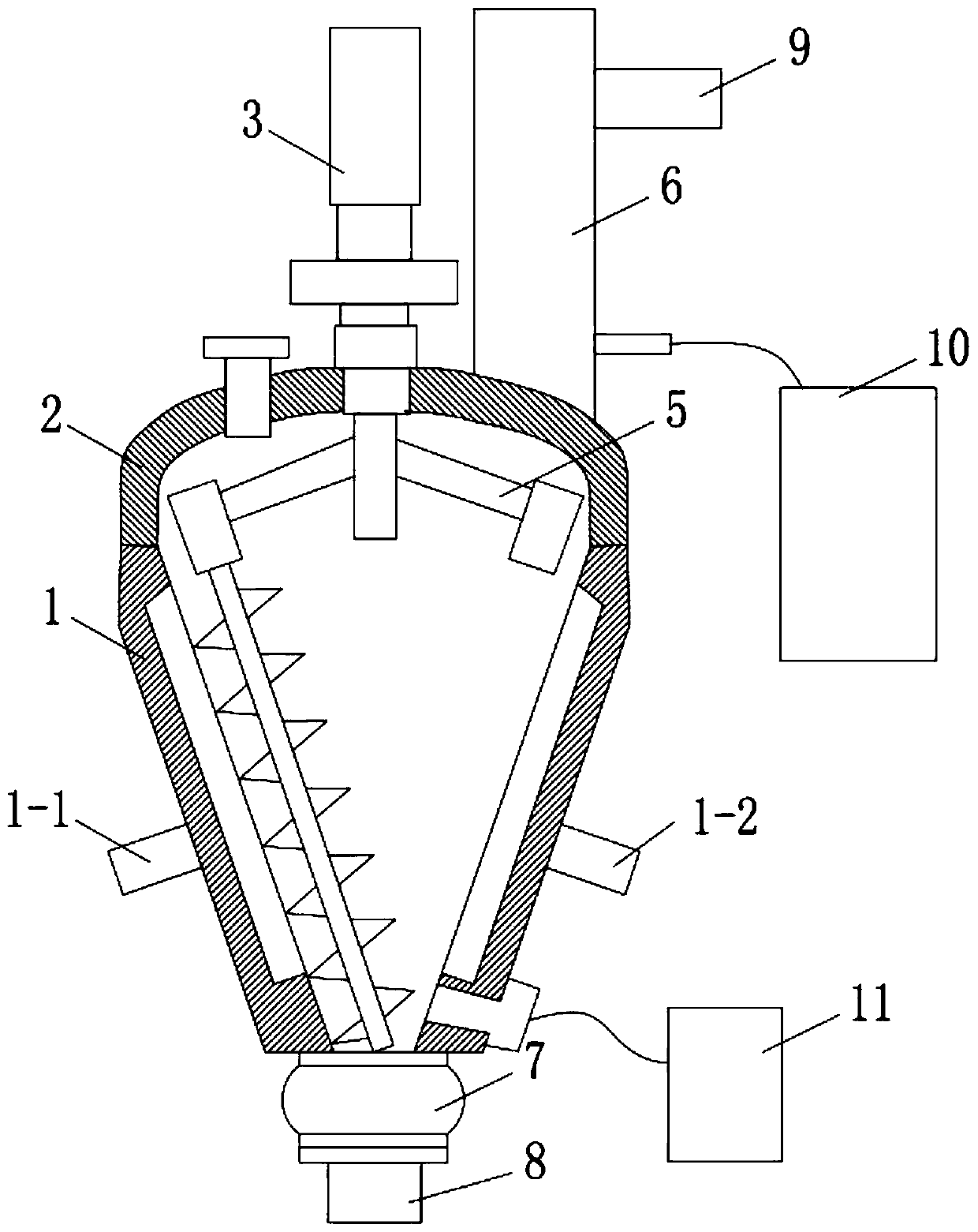
[0032] Such as figure 1 as shown,

[0033] The invention provides a conical drier for processing radioactive waste resin, comprising

[0034] The conical shell 1 is used to hold the waste resin. The conical shell 1 is a double-layer jacket structure with heat transfer oil in the middle. The side of the conical shell 1 is provided with a heat transfer oil inlet 1-1 and a cone Body heat transfer oil outlet 1-2, the heat transfer oil inlet 1-1 and heat transfer oil outlet 1-2 are respectively connected to the thermal oil unit through oil pipes;

[0035] The upper end cap 2 of the conical housing is arranged on the top of the conical housing 1 for sealing the conical ...


PUM


Abstract

The invention belongs to the technical field of radioactive waste treatment equipment, in particular to a conical dryer for treating waste resins with radioactivity. The conical dryer comprises a conical shell with a double jacket structure, a stirring device, a condenser, a discharge ball valve, a loading joint, an air exhaust device and a condensate tank, wherein heat-transfer oil flows in the middle of the conical shell; the side face of the conical shell is provided with a heat-transfer oil inlet and a cone heat-transfer oil outlet; the heat-transfer oil inlet and the heat-transfer oil outlet are separately connected with a hot oil unit through oil pipes; the top of the conical shell is provided with a conical shell upper end cover, and the conical shell upper end cover is provided with a first driving motor and a feed inlet; the stirring device is installed inside the conical shell, and the first driving motor is connected with the stirring device in a transmission mode; the condenser is arranged on the of the conical shell upper end cover and communicates with the inner side of the conical shell; the discharge ball valve is arranged at the lower end of the conical shell and communicates with the inner side of the conical shell; the loading joint is connected with the lower end of the discharge ball valve; the air exhaust device is connected with a condenser air outlet pipe; and the condensate tank is connected with a condensate drain pipe at the bottom of the condenser.

Description

technical field [0001] The invention belongs to the technical field of radioactive waste treatment equipment, in particular to a conical drier for treating radioactive waste resin. Background technique [0002] Radioactive waste refers to radioactive waste water, waste gas and solid waste. With the development of the atomic energy industry and the widespread use of radioactive isotopes, radioactive waste is increasing day by day. If it is discharged without treatment or improper treatment, the environment will be polluted by radioactivity, which will not only affect the growth of animals and plants, deteriorate water bodies, and endanger human health. Even have adverse effects on future generations. [0003] Under the circumstance that the treatment and disposal of radioactive waste is becoming more and more prominent, the traditional waste resin cement solidification process technology will greatly increase the final waste price and increase the capacity, which does not me...

Claims


Application Information

Patent Timeline
Patent Type & Authority Applications(China)
IPC IPC(8): F26B11/14F26B25/06F26B23/10F26B25/00F26B25/04F28B1/02F28F9/22F16K5/06F16K5/20G21F9/00G21F9/06
CPCF16K5/06F16K5/20F26B11/14F26B23/10F26B25/002F26B25/006F26B25/04F26B25/06F26B2200/04F28B1/02F28F9/22G21F9/008G21F9/06
Inventor 岳仁亮周宏宇张卫东郑继龙
Owner JIANGSU ZHONGHAI HUA HE ENVIRONMENTAL PROTECTION CO LTD
Why Eureka
Eureka Blog
Learn More