

Optical lens group
An optical lens and lens technology, applied in the field of optical lens sets, can solve problems such as the reduction of the illumination of the optical system
- Summary
- Abstract
- Description
- Claims
- Application Information
AI Technical Summary
Problems solved by technology
Method used
Image

Examples
Embodiment 1
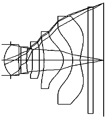
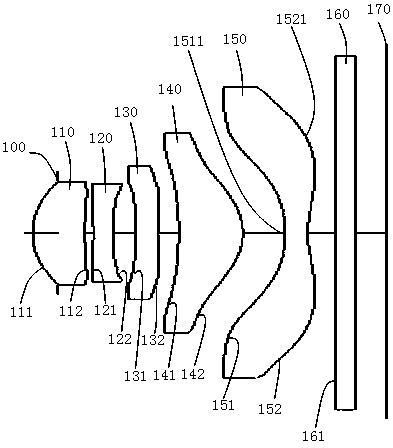
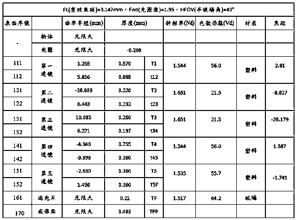
[0039] Example 1 as figure 1 and figure 2 As shown, the structure of each lens in the lens group refers to figure 2 As shown, the first lens 110, the second lens 120, the third lens 130, the fourth lens 140, and the fifth lens 150 are all made of plastic; 100 is an aperture arranged between the object side and the first lens 110; a plane lens 170 is an infrared filter made of glass.
[0040] In this example:
[0041] The first lens 110 has a positive refractive power;
[0042] The second lens 120 has a negative refractive power;
[0043] The third lens 130 has a negative refractive power;
[0044] The fourth lens 140 has positive refractive power, and the image side 141 is convex;
[0045] The fifth lens 150 has negative refractive power. The image side 151 includes a concave surface 1511 located near the optical axis, and the image side also includes at least one convex surface 1521 located near the circumference;
[0046] The object side 111 and the image side 112 o...
Embodiment 2
[0056] Embodiment 2 structure such as Figure 7 As shown, this embodiment uses similar symbols as those in Embodiment 1 to mark similar components, only changing the beginning of the mark to 2, wherein the convex and concave portions of the sides of objects and images are the same as those in Embodiment 1, for example, One lens 210 has an object side 211 , the first lens 210 has an image side 212 , and so on. Embodiment 2 differs from Embodiment 1 in the parameters of curvature radius, lens thickness, lens gap, lens refractive index, dispersion coefficient, and aspheric coefficient.
[0057] Figure 7 Draw a schematic diagram of the spherical aberration, astigmatism and distortion curves of three different wavelengths (486.1nm, 587.6nm, 656.3nm) in this implementation; Figure 7 The left side is the spherical aberration curve; Figure 6 The middle is a schematic diagram of the astigmatism curve; Figure 7 The right side is a schematic diagram of the distorted curve, from ...
Embodiment 3
[0059] Embodiment 3 structure such as Figure 10 As shown, this embodiment uses similar symbols as those in Embodiment 1 to mark similar components, only changing the beginning of the mark to 3, wherein the convex and concave portions of the sides of objects and images are the same as those in Embodiment 1, for example, A lens 310 has an object side 311 , a first lens 310 has an image side 312 , and so on. Embodiment 3 is different from Embodiment 1 in the parameters of radius of curvature, lens thickness, lens gap, lens refractive index, dispersion coefficient, lens focal length, and aspheric coefficient.
[0060] Figure 11 Draw a schematic diagram of the spherical aberration, astigmatism and distortion curves of three different wavelengths (486.1nm, 587.6nm, 656.3nm) in this implementation; Figure 11 The left side is the spherical aberration curve; Figure 11 The middle is a schematic diagram of the astigmatism curve; Figure 11 The right side is a schematic diagram of...
PUM
 Abstract
Description
Claims
Application Information