Optical imaging lens

A technology of optical imaging lens and imaging surface, applied in optics, optical components, instruments, etc., can solve the problem of difficult miniaturization of lens

Active Publication Date: 2021-12-07
ZHEJIANG SUNNY OPTICAL CO LTD
View PDF11 Cites 0 Cited by
  • Summary
  • Abstract
  • Description
  • Claims
  • Application Information

AI Technical Summary

Problems solved by technology

[0005] The main purpose of the present invention is to provide an optical imaging lens to solve the problem that the lens in the prior art is difficult to miniaturize

Method used


Image

  • Optical imaging lens
  • Optical imaging lens
  • Optical imaging lens

Examples


Embodiment 1

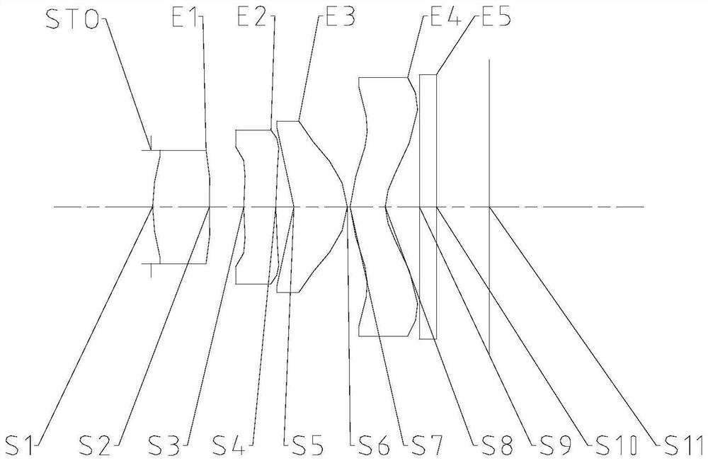
[0068] Such as Figure 1 to Figure 25 As shown, from the object side of the optical imaging lens to the image side of the optical imaging lens, the first lens, the second lens, the third lens and the fourth lens are included in sequence, the object side of the third lens is a concave surface, and the image of the third lens The side is convex; the fourth lens has negative refractive power; wherein, the maximum effective radius DT11 of the object side of the first lens and the aperture value fno of the optical imaging lens satisfy: 0.3mm

[0069] By rationally allocating the focal power of each lens, it is beneficial to balance the aberration generated by the optical imaging lens and greatly increase the imaging quality of the optical imaging lens. Reasonable design of the focal power and surface shape of the first lens and ...

Embodiment 2

[0090] Such as Figure 1 to Figure 25 As shown, from the object side of the optical imaging lens to the image side of the optical imaging lens, the first lens, the second lens, the third lens and the fourth lens are included in sequence, the object side of the third lens is a concave surface, and the image of the third lens The side is convex; the fourth lens has negative refractive power; wherein, the maximum effective radius DT11 of the object side of the first lens and the aperture value fno of the optical imaging lens satisfy: 0.3mm

[0091] By rationally allocating the focal power of each lens, it is beneficial to balance the aberration generated by the optical imaging lens and greatly increase the imaging quality of the optical imaging lens. Reas...


PUM


Abstract

The invention provides an optical imaging lens. The optical imaging lens sequentially comprises a first lens, a second lens, a third lens and a fourth lens from the object side to the image side of the optical imaging lens, wherein the object-side surface of the third lens is a concave surface, and the image-side surface of the third lens is a convex surface; the fourth lens has negative focal power; the maximum effective radius DT11 of the object-side surface of the first lens and the aperture value fno of the optical imaging lens meet the following condition: 0.3 mm < DT11/fno < 0.5 mm; and the effective focal length f of the optical imaging lens and the entrance pupil diameter EPD of the optical imaging lens meet the following condition: f/EPD < 2. The problem that a lens in the prior art is difficult to miniaturize is solved.

Description

technical field [0001] The present invention relates to the technical field of optical imaging equipment, in particular to an optical imaging lens. Background technique [0002] With the increasingly fierce competition among imaging digital consumer products, lenses with different functions are constantly being explored and iterated to improve customer trust and satisfaction. Among them, the TOF (Time-of-Flight) lens, by virtue of its unique advantages, has grown in an orderly manner in the market share, showing excellent potential. [0003] The TOF lens transmits and receives infrared signal pulses, and uses the acquired time difference or phase difference to perform inversion to reproduce the environmental depth information. Compared with structured light technology, TOF lenses have better blur capabilities, and have significant advantages in terms of calculation time and effective depth. If this technology is combined with a large aperture, it will have a faster camera ...

Claims


Application Information

Patent Timeline
Patent Type & Authority Applications(China)
IPC IPC(8): G02B13/00G02B13/18G03B30/00
CPCG02B13/004G02B13/18G03B30/00
Inventor 高劲柏宋立通金银芳戴付建赵烈烽
Owner ZHEJIANG SUNNY OPTICAL CO LTD
Why Eureka
Try Eureka