Large transformer mounting, hoisting and carrying machine and method

A transformer, large-scale technology, applied in the manufacture of inductors/transformers/magnets, electrical components, circuits, etc., can solve the problems of easy sliding, large ring size, falling, etc., to reduce impact force, prevent relative sliding, and facilitate The effect of installation work

Active Publication Date: 2019-11-08
JIANGSU BEICHEN HUBANG ELECTRIC POWER CO LTD
View PDF6 Cites 1 Cited by
  • Summary
  • Abstract
  • Description
  • Claims
  • Application Information

AI Technical Summary

Problems solved by technology

[0004] (1) The traction rope is directly hung on the lifting ring set on the transformer. Due to the large volume and weight of the transformer, the size of the lifting ring used is correspondingly large. If the lifting ring is directly fixed on the transformer, after the lifting work is completed or on the When the transformer is packaged and transported, the lifting ring will hinder the normal work;
[0005] (2) When the transformer is hoisted, its bottom is often supported by a wooden board, and only ropes are used to fasten the transformer and the wooden board. If the traction rope shakes during hoisting, the transformer and the wooden board are easily Slips and there is a risk of falling

Method used


Image

  • Large transformer mounting, hoisting and carrying machine and method
  • Large transformer mounting, hoisting and carrying machine and method
  • Large transformer mounting, hoisting and carrying machine and method

Examples


Embodiment Construction

[0036] The embodiments of the present invention will be described below with reference to the drawings. In this process, in order to ensure the clarity and convenience of the description, we may exaggerate the width of the line or the size of the constituent elements in the illustration.

[0037] In addition, the following terms are defined based on the functions of the present invention, and may be different according to the intentions or conventions of users and operators. Therefore, these terms are defined based on the entire content of this specification.

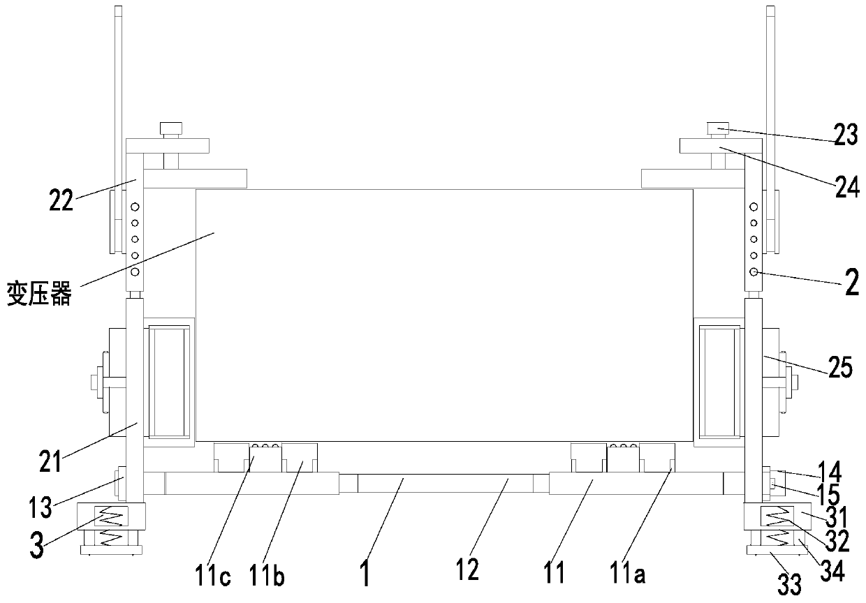
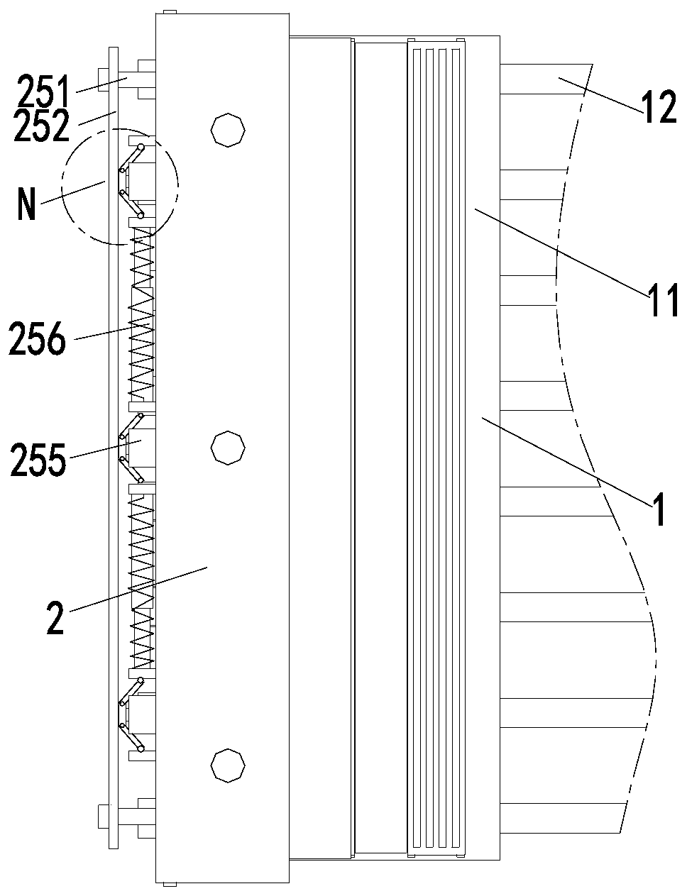
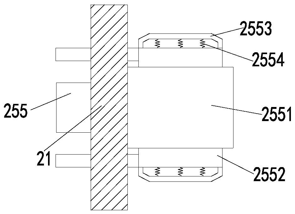
[0038] Such as Figure 1 to Figure 6 As shown, a large-scale transformer installation hoisting machine includes a support base 1, a limit frame 2 and a buffer base 3. The upper end of the support base 1 is arranged with a limit frame 2, and the lower end of the limit frame 2 is equipped with a buffer seat 3 , And the number of limit frames 2 is two, and the two limit frames 2 are arranged symmetrically; among them:

[0039]...


PUM


Abstract

The invention relates to a large transformer mounting, hoisting and carrying machine and method. The machine comprises a supporting seat, limiting frames and a buffer base; the limiting frames are arranged at the upper end of the supporting seat; the buffer base is installed at the lower ends of the limiting frames. The number of the limiting frames is two; the two limiting frames are symmetrically arranged left and right, each limiting frame comprises a vertical plate, a lifting plate, an adjusting bolt, an adjusting pressing plate and a limiting branched chain; the supporting seat comprisesa supporting plate, a connecting rod, a connecting plate, a fixing frame and a fixing bolt; the buffer base comprises a supporting block, a buffering spring, a buffering plate and an inserting plate,and the limiting branched chain comprises a distance adjusting plate, a distance adjusting bolt, a pressing plate, a distance adjusting block, a limiting block and a telescopic rod. The bottom of thetransformer is supported through the size-adjustable supporting seat, meanwhile, the side walls of the transformer are limited through the limiting frames, and sliding in a hoisting process is avoided; when the transformer lands, the buffer base makes contact with the ground firstly, and the effect of reducing impact force generated when the transformer lands on the ground is achieved.

Description

Technical field [0001] The invention relates to the technical field of power equipment installation, in particular to a large-scale transformer installation hoisting machine and method. Background technique [0002] Transformer is a static electrical equipment used to transform AC voltage and current to transmit AC power. It is based on the principle of electromagnetic induction to achieve power transfer. The role of the electric transformer is multifaceted, not only can increase the voltage to send the electric energy to the electricity consumption area, but also reduce the voltage to the voltage used at all levels to meet the needs of electricity. In short, both step-up and step-down must be completed by a transformer. [0003] Therefore, transformers are essential equipment in our daily life and work, and transformers need to be installed in various places. At present, the following problems exist in the hoisting process of large transformers: [0004] (1) The traction rope is ...

Claims


Application Information

Patent Timeline
Patent Type & Authority Applications(China)
IPC IPC(8): H01F41/00
CPCH01F41/00
Inventor 刘敏洁方坤棉
Owner JIANGSU BEICHEN HUBANG ELECTRIC POWER CO LTD
Why Eureka
Try Eureka