Isolating switch

A technology for isolating switches and fixing seats, which is applied in the direction of electric switches, air switch components, high-voltage air circuit breakers, etc., and can solve problems such as high force requirements of the driving mechanism, failure of circuit disconnection, and long gear rods, etc.

Inactive Publication Date: 2019-11-08
胡理取
View PDF1 Cites 3 Cited by
  • Summary
  • Abstract
  • Description
  • Claims
  • Application Information

AI Technical Summary

Problems solved by technology

As we all know, the isolating switch realizes the conduction of the circuit by connecting the left and right lugs through the knife switch. Therefore, the knife switch and the two lugs must be in full contact to ensure the current conduction between each other, and full contact means that the two lugs are in contact with each other. The existence of friction between the two, in the disconnection operation, when the driving mechanism drives the knife switch to swing downward, it needs to meet two forces at the same time to swing the knife switch downward. If the two forces are satisfied at the same time, the force applied to the driving mechanism will be too high, and it is easy to fail to disconnect the circuit due to insufficient force of the driving mechanism.
At the same time, the existing drive mechanism is long, takes up a large space, and is likely to cause the overall stability of the disconnector. For example, the Chinese patent patent number 201910065877.1, the application date is 2019.05.28, and the patent name is a disconnector with an anti-falling device. The disclosed drive Mechanism 7, which includes a housing and a fixed plate located in the housing, gears, motors, gear rods, etc. The gear rod needs to be set for a long time due to the isolation switch in the disconnected state.

Method used


Image

  • Isolating switch
  • Isolating switch
  • Isolating switch

Examples


Embodiment Construction

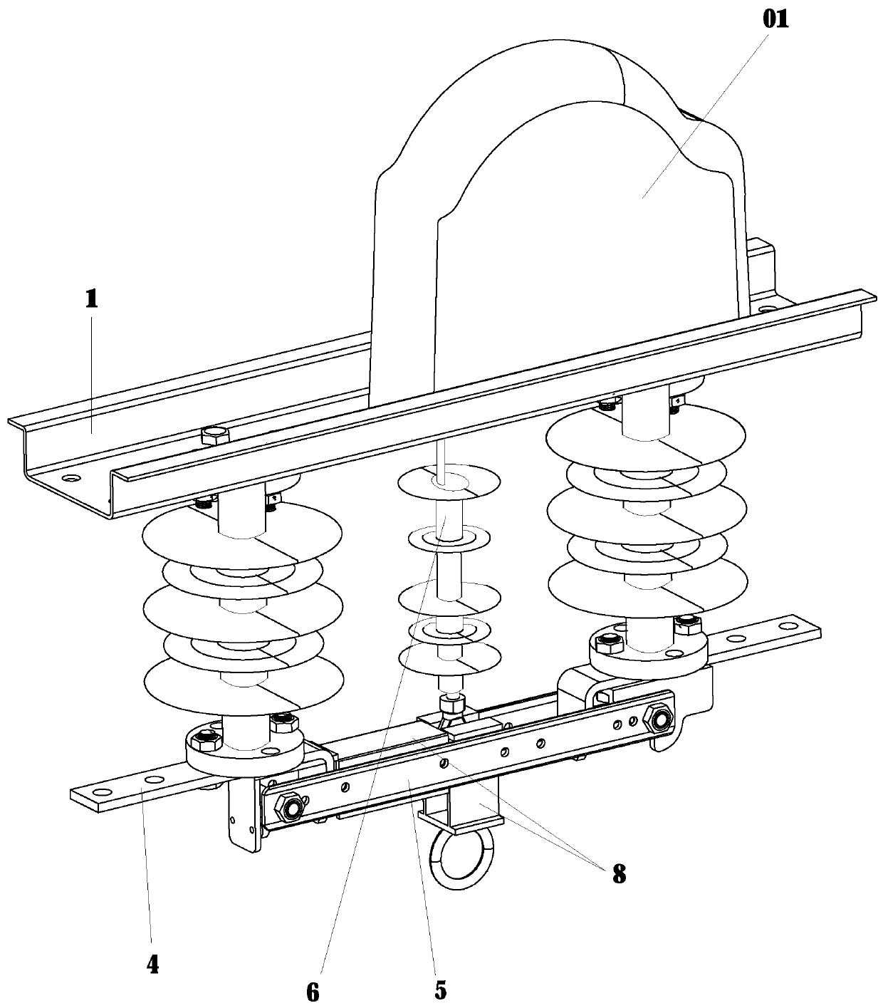
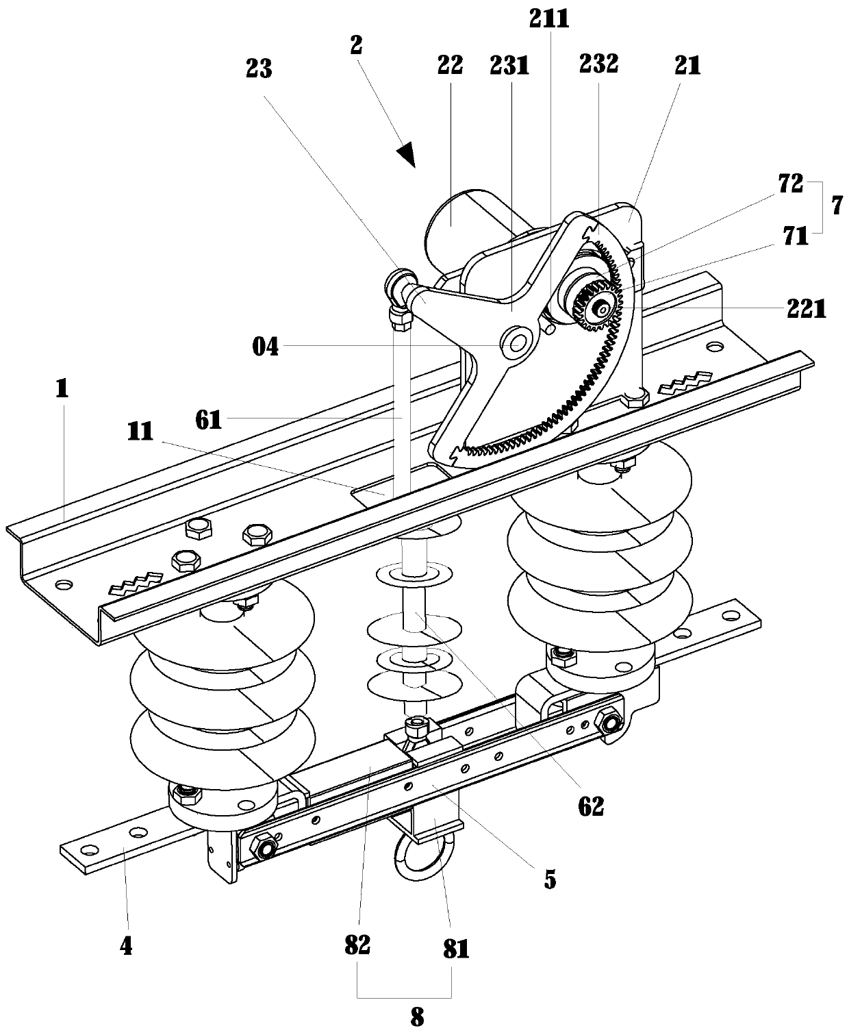
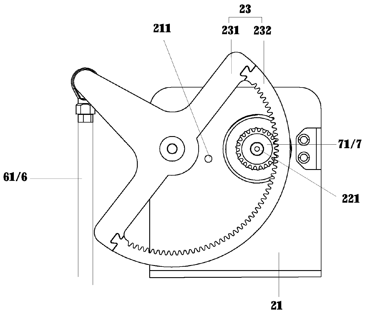
[0029] refer to Figure 1 to Figure 12 It can be seen that the present invention: a disconnector, including a fixed seat 1, a drive mechanism 2 located above the fixed seat 1, two parallel insulators 3 and a knife switch 5 located below the fixed seat 1, one end of the knife switch 5 is hinged to one of the insulators 3 At the end away from the fixed seat 1, the ends of the two insulators 3 away from the fixed seat 1 are fixed with lugs 4, and the two lugs 4 are turned on or off through the swing of the knife switch 5, and the driving mechanism 2 passes through the connecting rod. 6. Connect and drive the knife switch 5 to swing. The driving mechanism 2 includes a fixed plate 21, a motor 22 and a bracket 23. The motor 22 is connected to an output shaft 221. The bracket 23 includes a body 231 and an arc-shaped rack 232. The arc-shaped rack 232 Mesh with the output shaft 221 through the buffer assembly 7, the buffer assembly 7 includes a gear 71 and a transition wheel 72, the tr...


PUM


Abstract

The invention relates to an isolating switch, which comprises a fixing seat, a driving mechanism, a row insulator and a switch. Connection or disconnection of two wiring pieces is realized through swinging of the switch; the driving mechanism is connected with and drives the switch to swing through a connecting rod; the driving mechanism comprises a fixing plate, a motor and a support, and the support comprises a body and an arc rack; and the connecting rod is connected with an anti-drop device. Through using the arc rack to replace the original straight rack, the occupied space of the isolating switch is reduced; an arc slot gives the motor output shaft enough travel to speed up, and the switch is ensured to be pushed or pulled under a sufficient instantaneous starting force. When the switch needs to be disconnected, the driving mechanism gives the anti-drop device a downward force through the connecting rod, an inserting rod inserted to a lap joint hole is retracted and locked, a friction force with the wiring piece is given to the switch to realize disconnection of the switch, and segmented force application is realized.

Description

technical field [0001] The invention relates to the technical field of power system equipment, in particular to an isolating switch. Background technique [0002] The isolating switch is an important device for realizing separation, converting line power and ensuring the safety of power failure maintenance. When an emergency needs to be disconnected immediately, if the operation cannot be completed in time, it may cause immeasurable disasters. The existing isolating switch pushes the knife switch through a driving mechanism to make it swing around its hinge point, thereby opening to cut off the circuit. As we all know, the isolating switch realizes the conduction of the circuit by connecting the left and right lugs through the knife switch. Therefore, the knife switch and the two lugs must be in full contact to ensure the current conduction between each other, and full contact means that the two lugs are in contact with each other. The existence of friction between the two...

Claims


Application Information

Patent Timeline
Patent Type & Authority Applications(China)
IPC IPC(8): H01H31/02H01H21/36
CPCH01H21/36H01H31/026
Inventor 章琼渊唐凯胡理取
Owner 胡理取
Why Eureka
Try Eureka