Steel component spraying device easy to fix on site

A technology of spraying device and steel components, applied in the direction of spraying device, etc., can solve the problems of inconvenience to use on construction site, inconvenient spraying of steel components, troublesome fixed installation method, etc.

Pending Publication Date: 2019-11-12
JIANGXI FUHUANG STEEL STRUCTURE CO LTD
View PDF0 Cites 2 Cited by
  • Summary
  • Abstract
  • Description
  • Claims
  • Application Information

AI Technical Summary

Problems solved by technology

[0004] The purpose of the present invention is to solve the problem that the existing design has large volume, fixed structure, inconvenient spraying work on steel components, troublesome fixed installation method, and inconvenient use on the construction site. Component spraying device, which can be conveniently and quickly fixed and installed on the steel component to be sprayed, and the user can simply and conveniently adjust the position of the spraying mechanism to spray the steel component

Method used


Image

  • Steel component spraying device easy to fix on site
  • Steel component spraying device easy to fix on site
  • Steel component spraying device easy to fix on site

Examples


Embodiment 1

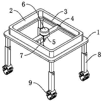
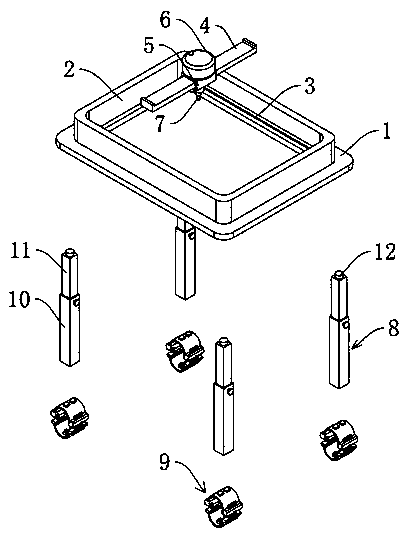
[0029] See Figure 1-2 , A spraying device for steel components that is easy to fix on site, including a connecting plate 1 and a mounting plate 2. The mounting plate 2 is fixedly connected to the connecting plate 1, and the inner wall of the mounting plate 2 is provided with a chute 3, which slides on the chute 3. A mounting frame 4 is connected, a connecting sleeve 5 is slidably installed on the mounting frame 4, a paint storage tank 6 is fixedly connected to the upper surface of the connecting sleeve 5, and a spraying mechanism 7 is fixedly installed on the lower surface of the connecting sleeve 5. The paint storage tank 6 is matched; the lower surface of the connecting plate 1 is connected with a supporting mechanism 8. The supporting mechanism 8 includes a supporting rod 10 and a telescopic rod 11. The telescopic rod 11 is telescopically connected to the supporting rod 10, and the top of the telescopic rod 11 is fixedly installed The bearing 12 is connected, the supporting ...

Embodiment 2

[0032] See Figure 3-6 , Based on Example 1, the difference is:

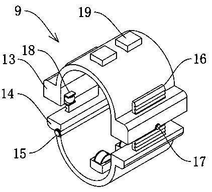
[0033] The fixed connection mechanism 9 includes an upper fixing portion 13 and a lower fixing portion 14. The upper fixing portion 13 includes an upper connecting block and an upper fixing arc tube, and the lower fixing portion 14 includes a lower connecting block and a lower fixing arc tube. A hinge 15 is fixedly installed on the edge of the lower end, and the lower fixed arc tube is movably connected with the lower connecting block through the hinge 15.

[0034] The lower connecting block is fixedly connected to the limiting tooth plate 16, the upper connecting block is provided with a through groove 20, the through groove 20 matches the limiting tooth plate 16, and the inside of the upper connecting block is also installed with a limiting adjusting mechanism 17 near the through groove 20 , The limit adjustment mechanism 17 is matched with the limit tooth plate 16; the upper connecting block is also provided with ...

Embodiment 3

[0038] Reference Figure 7-8 ; Based on embodiment 1 or 2, the difference is that;

[0039] The lateral movement mechanism 18 includes a first connecting frame 27. The inside of the first connecting frame 27 is provided with a spherical roller 28. The spherical roller 28 is fixedly connected with a protruding shaft 29. The spherical roller 28 is rotatably connected to the first connecting frame through the protruding shaft 29. On the frame 27, a second spring 30 is fixedly connected to the outer wall surface of the first connecting frame 27, and one end of the second spring 30 away from the first connecting frame 27 is fixedly connected to the inner wall of the mounting groove 21.

[0040] The longitudinal movement promoting mechanism 19 includes a connecting cover 31, which is fixedly connected to the upper fixed arc tube or the lower fixed arc tube. A second connecting frame 32 is provided inside the connecting cover 31, and a groove is rotatably connected to the second connectin...


PUM


Abstract

The invention discloses a steel component spraying device easy to fix on site, and belongs to the technical field of steel component processing devices. The steel component spraying device easy to fixon site comprises a connecting plate and a mounting plate, wherein the mounting plate is fixedly connected to the connecting plate, a sliding groove is formed in the inner wall of the mounting plate,a mounting frame is slidably connected to the sliding groove, a connecting sleeve is slidably mounted on the mounting frame, a coating storage tank is fixedly connected to the upper surface of the connecting sleeve, a spraying mechanism is fixedly installed on the lower surface of the connecting sleeve, and the spraying mechanism is matched with the coating storage tank; and a supporting mechanism is connected with the lower surface of the connecting plate, and comprises a supporting rod and a telescopic rod, the telescopic rod is in telescopic connection with the supporting rod, and a connecting bearing is fixedly installed at the top end of the telescopic rod. According to the device, the problems that existing design is large in size, fixed in structure, inconvenient in steel componentspray, troublesome to fix and mount and inconvenient to use on the construction site are effectively solved.

Description

Technical field [0001] The invention relates to the technical field of steel component processing devices, in particular to a steel component spraying device that is easy to fix on site. Background technique [0002] At present, with the rapid development of the steel structure industry, the structural forms used in public venues and industrial plants such as airports, stadiums, museums, etc. are becoming more and more complex and diverse; however, due to the different shapes of steel structures, the conditions of the construction site are different. In the process, it is often necessary to make corresponding processing work to the steel components, and during the spraying work, one of the more common tasks in the processing of steel components, currently it is often used by workers to hold the spraying tool to spray the steel components. The work weight is relatively large, and the labor intensity of manual spraying work is relatively large and the efficiency is low. Therefore, ...

Claims


Application Information

Patent Timeline
Patent Type & Authority Applications(China)
IPC IPC(8): B05B15/62B05B15/628B05B13/04B05B15/68
CPCB05B13/041B05B15/62B05B15/628B05B15/68
Inventor 许启龙解成松
Owner JIANGXI FUHUANG STEEL STRUCTURE CO LTD
Why Eureka
Try Eureka