Manual workshop cloth winding machine

A winding machine and cloth technology, applied in the direction of winding strips, thin material handling, transportation and packaging, etc., can solve the problems of uneven cloth, troublesome operation, etc.

Active Publication Date: 2019-11-12
胡少欢
View PDF8 Cites 2 Cited by
  • Summary
  • Abstract
  • Description
  • Claims
  • Application Information

AI Technical Summary

Problems solved by technology

[0003] In order to overcome the disadvantages of holding the cylinder with one hand and rolling the fabric on the cylinder with the other hand, the operation is more troublesome, and the fabric is in a relaxed state during winding, which may easily lea

Method used


Image

  • Manual workshop cloth winding machine
  • Manual workshop cloth winding machine
  • Manual workshop cloth winding machine

Examples


Embodiment 1

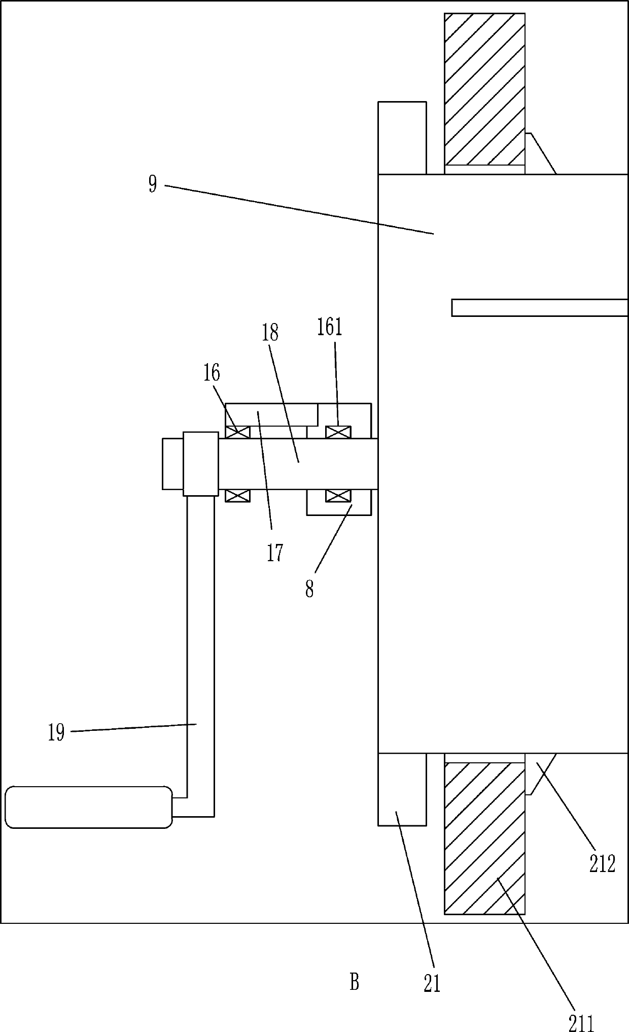
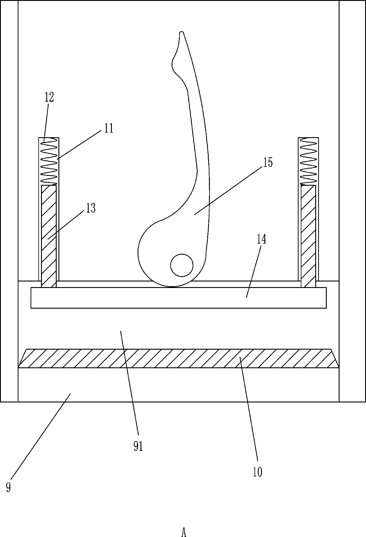
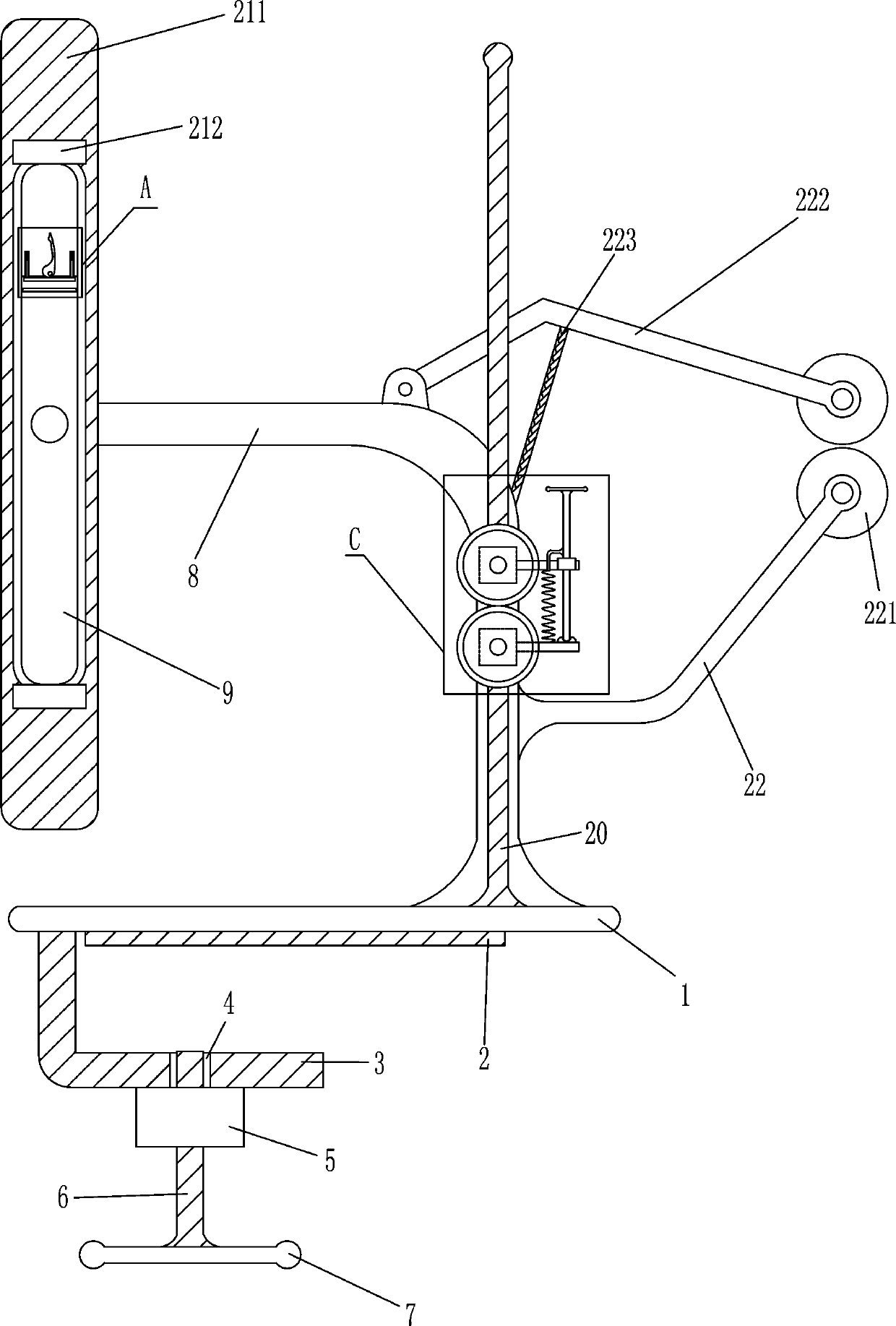
[0018] A hand workshop fabric winder, such as Figure 1-4 As shown, it includes a base 1, a fixing device, a support column 8, a square plate 9, a friction block 10, a first spring 12, a guide rod 13, a pressure plate 14, an eccentric rod 15, a first bearing seat 16, and a second bearing seat 161 , reinforcing rib 17, rotating shaft 18 and rocking handle 19, the left side of the bottom of the base 1 is provided with a fixing device that can fix the device, the right side of the top of the base 1 is fixedly connected with a support column 8, and the base 1 is connected to the support column by welding 8 connection, the middle of the left end of the support column 8 is fixedly connected with the second bearing seat 161, the upper rear side of the left end of the support column 8 is fixedly connected with the reinforcing rib 17, and the rear side of the bottom of the reinforcing rib 17 is fixedly connected with the first bearing seat 16, the first bearing seat 16 and the second b...

Embodiment 2

[0020] A hand workshop fabric winder, such as Figure 1-4 As shown, it includes a base 1, a fixing device, a support column 8, a square plate 9, a friction block 10, a first spring 12, a guide rod 13, a pressure plate 14, an eccentric rod 15, a first bearing seat 16, and a second bearing seat 161 , reinforcing rib 17, rotating shaft 18 and rocking handle 19, the left side of base 1 bottom is provided with the fixing device that this device can be fixed, base 1 top right side is affixed with support column 8, and the middle of support column 8 left ends is affixed with second Bearing seat 161, reinforcing rib 17 is fixedly connected to the upper rear side of the left end of support column 8, the first bearing seat 16 is fixedly connected to the rear side of the bottom of reinforcing rib 17, and the rotating shaft 18 is connected between the first bearing seat 16 and the second bearing seat 161 , the square plate 9 that can be rolled up to the cloth is installed on the front end...

Embodiment 3

[0023] A hand workshop fabric winder, such as Figure 1-5 As shown, it includes a base 1, a fixing device, a support column 8, a square plate 9, a friction block 10, a first spring 12, a guide rod 13, a pressure plate 14, an eccentric rod 15, a first bearing seat 16, and a second bearing seat 161 , reinforcing rib 17, rotating shaft 18 and rocking handle 19, the left side of base 1 bottom is provided with the fixing device that this device can be fixed, base 1 top right side is affixed with support column 8, and the middle of support column 8 left ends is affixed with second Bearing seat 161, reinforcing rib 17 is fixedly connected to the upper rear side of the left end of support column 8, the first bearing seat 16 is fixedly connected to the rear side of the bottom of reinforcing rib 17, and the rotating shaft 18 is connected between the first bearing seat 16 and the second bearing seat 161 , the square plate 9 that can be rolled up to the cloth is installed on the front end...


PUM


Abstract

The invention relates to a winding machine, in particular to a manual workshop cloth winding machine. The manual workshop cloth winding machine can facilitate cloth winding by workers, the convenienceis achieved, cloth can be tightened, and disorderly cloth winding is avoided. According to the technical scheme, the manual workshop cloth winding machine comprises a base, a fixing device, a supporting column, a square plate, a friction block, a first spring, a guide rod, a pressing plate, an eccentric rod and the like, wherein the fixing device capable of fixing the machine is arranged on the left side of the bottom of the base, and the supporting column is fixedly connected to the right side of the top of the base. According to the machine, the cloth head end is moved to a slotted hole tobe pressed and fixed through the pressing plate, then a rocking handle is shaken, so that the square plate can reversely rotate so that the cloth can be wound, the condition that a person holds a reelbody by one hand, and winds the cloth around the reel body by the other hand is avoided, the convenience is achieved, the cloth can be more tightly wound by the effect of a first reel, so that the cloth is prevented from being disorderly wound.

Description

technical field [0001] The invention relates to a winding machine, in particular to a cloth winding machine for a manual workshop. Background technique [0002] In the manual workshop, a lot of materials need to be used, but the fabrics are generally piled up together, which is inconvenient for subsequent use. The fabric needs to be rolled up. Usually, people hold the cylinder with one hand and roll the fabric with the other. Rolling on the cylinder is cumbersome to operate, and the fabric is in a relaxed state during winding, which may easily cause the rolled fabric to be uneven, so another person is needed to help hold the cylinder, and the other person rolls the fabric on the cylinder , and the fabric is tightened, so the labor cost is high and laborious. Contents of the invention [0003] In order to overcome the disadvantages of holding the cylinder with one hand and rolling the fabric on the cylinder with the other hand, the operation is more troublesome, and the fa...

Claims


Application Information

Patent Timeline
IPC IPC(8): B65H18/10B65H18/08
CPCB65H18/08B65H18/10B65H2701/19
Inventor 邱金娣
Owner 胡少欢
Why Eureka
Try Eureka