Highway subgrade pressure resistance test device

A test device and anti-pressure technology, which is applied in the field of foundation soil survey, infrastructure engineering, construction, etc., can solve the problems of poor integrity of the detection device, rollover of the detection device, etc., and achieve high integrity, uniform and stable pressure, and increase the overall effect

Active Publication Date: 2019-11-12
何明
5 Cites 0 Cited by

AI-Extracted Technical Summary

Problems solved by technology

[0004] The adjustment of the stress area of ​​the existing detection device is generally carried out by connecting an external connection plate on its base. After this adjustment met...

Method used

During work, first adjust the height of moving block 3, make moving block 3 be locked on the suitable fixed screw hole 21 on column 2, the chute on column 2 can play the effect of position-limiting to moving block 3, and The fixed screw hole 21 on the column 2 can enable the moving block 3 to be locked at a specific height, and the position of the locking plate 5 will change after the height of the moving block 3 changes, so that the locking plate 5 can be locked on the outer support plate in a proper position 8, so that the support plate 1 and the outer support plate 8 form different sizes, so that the pressure receiving surface of the present invention can be in a suitable area, and the lower end of the present invention can be evenly supported by the connection between the locking plate 5 and the outer support plate 8. force, the locking plates 5 located at the front and rear ends of the column 2 can lock the two outer support plates 8 to increase the integrity of the present invention, and then the support plate 1 is locked and connected to the sides of the outer support plates 8 through ...

Abstract

The invention relates to a highway subgrade pressure resistance test device. The highway subgrade pressure resistance test device comprises a supporting plate, a vertical column, a moving block, sidesupporting rods, locking plates, connecting rods and a bearing plate; threaded holes are formed in the outer end of the supporting plate symmetrically, the vertical column is installed on the upper end surface of the supporting plate, the moving block is of a hollow square column structure, the moving block is located on the outer side of the middle part of the middle column, the connecting rods are symmetrically mounted at the top of the moving block, and the bearing plate is mounted at the top of the connecting rods; and the side supporting rods are symmetrically distributed at the bottom ofthe outer end of the moving block, the side supporting rods are arranged obliquely, the tops of the side supporting rods are connected to the bottom of the moving block through a hinge, and the locking plates are installed at the bottoms of the side supporting rods through hinges. The highway subgrade pressure resistance test device can solve the problems that an existing detecting device is poorin overallity after adjusting the force receiving area of the detecting device and the detecting device can possibly roll over due to uneven force during subgrade pressure resistance detection.

Application Domain

In situ soil foundation

Technology Topic

EngineeringLocking plate +4

Image

  • Highway subgrade pressure resistance test device
  • Highway subgrade pressure resistance test device
  • Highway subgrade pressure resistance test device

Examples

  • Experimental program(1)

Example Embodiment

[0025] In order to make the technical means, creative features, goals and effects achieved by the present invention easy to understand, the present invention will be further described below in conjunction with specific illustrations. It should be noted that, in the case of no conflict, the embodiments in the present application and the features in the embodiments can be combined with each other.
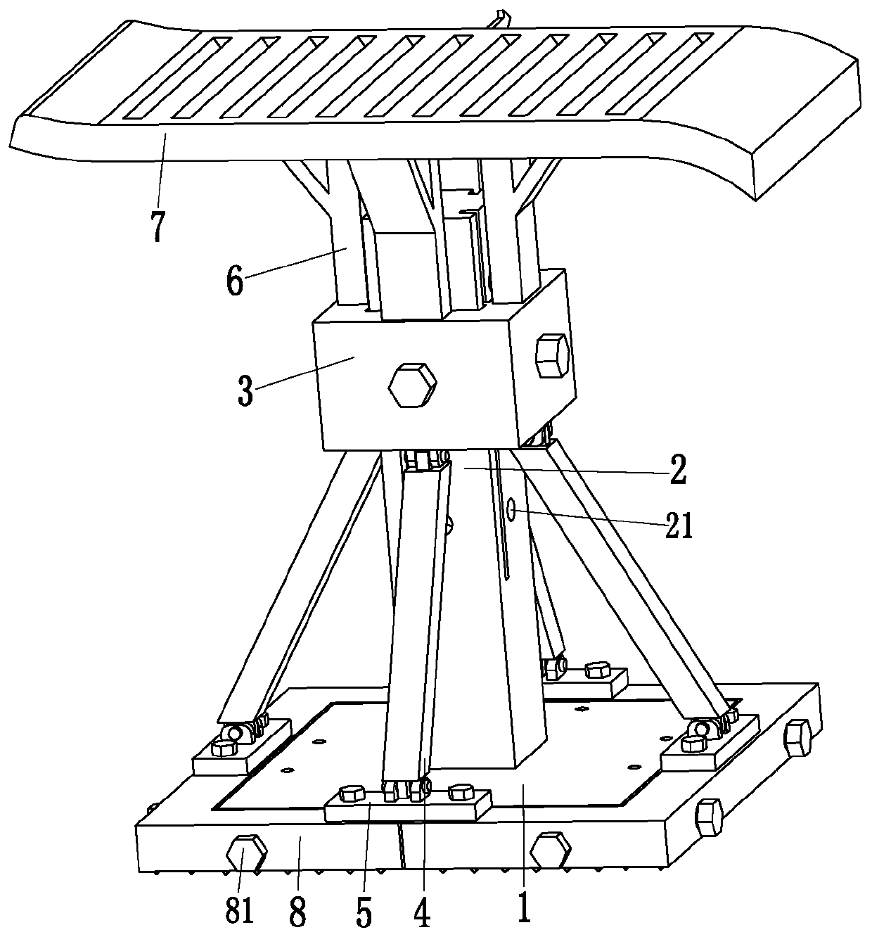
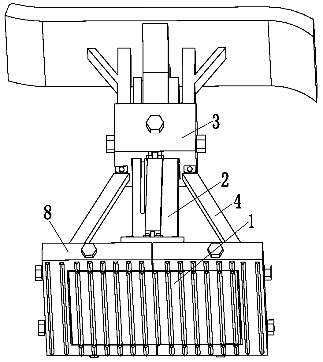
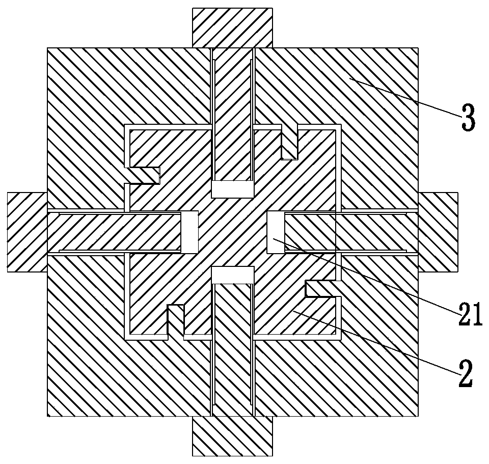
[0026] like Figure 1 to Figure 6 As shown, a roadbed anti-pressure test device includes a support plate 1, a column 2, a moving block 3, a side support rod 4, a locking plate 5, a connecting rod 6 and a pressure bearing plate 7, and the outer surface of the support plate 1 Threaded holes are arranged symmetrically on the end, a column 2 is installed on the upper end surface of the middle part of the support plate 1, the moving block 3 is a hollow square column structure, the moving block 3 is located outside the middle part of the column 2, and the top of the moving block 3 is symmetrically installed. The connecting rod 6 and the pressure bearing plate 7 are installed on the top of the connecting rod 6, and there are side struts 4 symmetrically distributed on the bottom of the outer end of the moving block 3. The bottoms of the blocks 3 are connected, and a locking plate 5 is installed through a hinge on the bottom of each side strut 4. By adjusting the position of the moving block 3, the side struts 4 can adjust the inclination, thereby changing the locking plate 5. In the support position, when an external engineering vehicle drives on the pressure bearing plate 7, the support plate 1 can be evenly stressed.
[0027] The outer end of the outer surface of the column 2 is symmetrically provided with a chute, the inner end of the moving block 3 is provided with a slider that matches the upper chute of the column 2, and the middle part of the outer surface of the column 2 is provided with fixed screw holes 21 , the fixed screw holes 21 are evenly arranged vertically, and the moving block 3 is installed in the fixed screw holes 21 on the column 2 through bolts. During specific work, the chute on the column 2 can limit the position of the moving block 3 The moving block 3 can be locked in the fixing screw hole 21 on the outer surface of the column 2, so that the moving block 3 can be locked at a specific height.
[0028] The left and right ends of the support plate 1 are distributed with a plurality of outer braces 8, the outer braces 8 are U-shaped structures, the size of the outer braces 8 increases sequentially from the inside to the outside, and the outer braces at the left and right ends 8 are symmetrically arranged, and the two outer support plates 8 corresponding to the positions are spliced ​​into a square frame structure, and the square frame structure formed by splicing the innermost outer support plates 8 is closely attached to the outer surface of the support plate 1, and the outer support plates The height of 8 corresponds to the height of support plate 1;
[0029] - A threaded hole is arranged longitudinally on the outer end of the outer support plate 8, and a threaded hole is distributed on the front and rear sides of the inner end of the pressure bearing plate 8, and the locking plates 5 located at the left and right ends of the column 2 are respectively installed on the outer ends of the outer support plate 8 by bolts In the threaded holes, the locking plates 5 located at the front and rear ends of the column 2 are respectively installed between the threaded holes at the inner ends of the two pressure bearing plates 8 through bolts. When inside, the position of the locking plate 5 will change, so that the locking plate 5 can be locked on the outer support plate 8 in a suitable position, so that the support plate 1 and the outer support plate 8 form different sizes, thereby changing the force bearing area of ​​the present invention , the larger the area formed by the support plate 1 and the outer support plate 8 is, the more it is pressed outward, so that the lower end of the present invention is evenly stressed, and the locking plates 5 located at the front and rear ends of the column 2 can lock the two outer support plates 8, Adds to the integrity of the invention.
[0030] The right end of the pressure bearing plate 7 is a concave arc structure, the left end of the pressure bearing plate 7 is an upturned arc structure, the top of the pressure bearing plate 7 is uniformly provided with toothed grooves, and the right end of the pressure bearing plate 7 is The concave arc-shaped structure can not hinder the external pressure-applying engineering vehicle from driving on the pressure-bearing plate 7, and the upturned arc-shaped structure at the left end of the pressure-bearing plate 7 can be used for external engineering vehicles when certain subsidence occurs in the present invention. To play the role of conduction, the toothed grooves on the pressure bearing plate 7 prevent the vehicle from slipping on the pressure bearing plate 7 .
[0031] The bottom of the support plate 1 and the bottom of the outer support plate 8 are provided with tooth-shaped protrusions, and the tooth-shaped protrusions provided on the support plate 1 and the outer support plate 8 enable the present invention to be supported on the foundation, increasing the strength of the present invention. stability.
[0032]A circular hole is provided on the outer end side of each outer support plate 8, a circular hole is provided on the front and rear sides of the inner end of each outer support plate 8, and connecting screws are arranged symmetrically on the side of the support plate 1. hole, the outer support plate 8 is installed on the connecting screw hole of the support plate 1 through the connecting bolt 81, the connecting bolt 81 can connect and lock the support plate 1 and the outer support plate 8, when the locking plate 5 is locked on different outer support plates When the plate 8 is on, the connecting bolt 81 can be replaced by a type, so that a plurality of outer support plates 8 are connected with the support plate 1 .
[0033] The size of the round hole on the outer support plate 8 is greater than the size of the connecting screw hole on the support plate 1, the size of the outer end of the connecting bolt 81 is greater than the size of its inner end, and the outer end of the connecting bolt 81 is connected to the circle on the outer support plate 8. The hole is a sliding fit, and the sliding fit between the outer end of the connecting bolt 81 and the round hole on the outer support plate 8 can increase the stability when the outer support plate 8 is locked on the support plate 1 .
[0034] A pointer is arranged on the rear side of the pressure bearing plate 7, and the pointer at the rear end of the pressure bearing plate 7 can point to the height of the pressure bearing plate 7, so that the artificial can intuitively check the sinking height of the present invention.
[0035] When working, first adjust the height of the moving block 3 so that the moving block 3 is locked on the appropriate fixed screw hole 21 on the column 2, the chute on the column 2 can limit the position of the moving block 3, and the upper column 2 The fixed screw hole 21 of the fixed block can make the moving block 3 lock at a specific height, and the position of the locking plate 5 will change after the height of the moving block 3 changes, so that the locking plate 5 can be locked on the outer support plate 8 at a suitable position, Make the support plate 1 and the outer support plate 8 form different sizes, so that the pressure receiving surface of the present invention can be in a suitable area, and the lower end of the present invention can be evenly stressed under the connection between the locking plate 5 and the outer support plate 8. The locking plates 5 at the front and rear ends of the column 2 can lock the two outer struts 8 to increase the integrity of the present invention, and then the support plate 1 and the sides of the outer struts 8 are locked and connected by connecting bolts 81, and the connecting bolts 81 The sliding fit between the outer end and the round hole on the outer support plate 8 can increase the stability when the outer support plate 8 is locked on the support plate 1;
[0036] After the compression area of ​​the present invention is adjusted, the present invention is placed in the subgrade pit, and the tooth-shaped protrusions provided on the support plate 1 and the outer support plate 8 enable the present invention to be supported on the foundation, increasing the stability of the present invention. Then the external engineering vehicle is controlled to pass by on the pressure bearing plate 7, and the concave arc structure at the right end of the pressure bearing plate 7 can not hinder the external pressure engineering vehicle from driving on the pressure bearing plate 7, and the upper part of the pressure bearing plate 7 left end The warped arc-shaped structure can play a role of conduction to the external engineering vehicles when the present invention sinks to a certain extent. The toothed grooves on the pressure bearing plate 7 place the phenomenon that the vehicle slips on the pressure bearing plate 7, and then Observe the height change of the pointer at the rear end of the pressure bearing plate 7, thereby completing the anti-pressure detection of the roadbed.
[0037] The present invention can quickly adjust the stress-bearing area of ​​the subgrade anti-pressure detection device, so that the pressure-receiving surface of the detection device can be in the required area. After adjustment, the pressure-receiving surface of the present invention has high integrity, strong stability, and The pressure on the surface is uniform and stable, and the detection effect of the invention on the pressure resistance of the roadbed is improved.
[0038] The basic principles, main features and advantages of the present invention have been shown and described above. Those skilled in the art should understand that the present invention is not limited by the above-mentioned embodiments. The descriptions in the above-mentioned embodiments and the specification only illustrate the principles of the present invention. Without departing from the spirit and scope of the present invention, the present invention will also There are various changes and improvements which fall within the scope of the claimed invention. The protection scope of the present invention is defined by the appended claims and their equivalents.

PUM

no PUM

Description & Claims & Application Information

We can also present the details of the Description, Claims and Application information to help users get a comprehensive understanding of the technical details of the patent, such as background art, summary of invention, brief description of drawings, description of embodiments, and other original content. On the other hand, users can also determine the specific scope of protection of the technology through the list of claims; as well as understand the changes in the life cycle of the technology with the presentation of the patent timeline. Login to view more.

Similar technology patents

Switching method, device and system

ActiveCN101998330Aimprove integrity
Owner:DATANG MOBILE COMM EQUIP CO LTD

Assembled mortise and tenon bracket type beam-column joint connecting device

PendingCN112942945AIncreased shear strengthimprove integrity
Owner:SHAOXING UNIVERSITY

Single-plant tree skeleton point extraction method, device and equipment and storage medium

PendingCN109712229Aimprove integrityreduce the number of cycles
Owner:漳州通正勘测设计院有限公司

Classification and recommendation of technical efficacy words

  • quick adjustment
  • improve integrity

Steel rail space adjuster

Owner:郑州铁路利达实业有限公司

Adjusting device of LED (Light-Emitting Diode) light source

Owner:成都启臣微电子股份有限公司

Regulating device for polishing diameter of polisher

InactiveCN103084958Aquick adjustmentWide range of processing
Owner:ZHANGJIAGANG KING MACC MACHINERY MFG

Virtual building accessory model hitching method and device, processor and terminal

PendingCN110197534Aquick adjustmentmore urban atmosphere
Owner:NETEASE HANGZHOU NETWORK

CT integrated respiratory monitor

InactiveUS7182083B2improve integrityeasy to train
Owner:KONINKLIJKE PHILIPS ELECTRONICS NV

GPS/INS vehicle attitude system

InactiveUS20050137799A1improve integritylow-cost
Owner:THE BOARD OF TRUSTEES OF THE LELAND STANFORD JUNIOR UNIV

Vehicle body structure

ActiveUS20050212333A1minimize local deformationimprove integrity
Owner:NISSAN MOTOR CO LTD

Textile for connection of electronic devices

InactiveUS20100013406A1improve integritystrong weave
Owner:KONINKLIJKE PHILIPS ELECTRONICS NV
Why Eureka
Try Eureka