
Total-travel regulating pneumatic valve

A pneumatic valve, full-stroke technology, applied to valve details, valve devices, engine components, etc., to achieve the effect of saving cost and production cycle

Pending Publication Date: 2019-11-12
SHANGHAI JULIANG VALVE GRP CO LTD
View PDF0 Cites 3 Cited by
  • Summary
  • Abstract
  • Description
  • Claims
  • Application Information

AI Technical Summary

Problems solved by technology

[0004] The purpose of the present invention is to provide a full-stroke adjustable pneumatic valve to solve the problem that the stroke adjustment of the pneumatic actuator can only be adjusted at two positions of 0 degrees and 90 degrees proposed in the background technology.

Method used


Image

  • Total-travel regulating pneumatic valve
  • Total-travel regulating pneumatic valve
  • Total-travel regulating pneumatic valve

Examples


Embodiment Construction

[0020] The following will clearly and completely describe the technical solutions in the embodiments of the present invention with reference to the accompanying drawings in the embodiments of the present invention. Obviously, the described embodiments are only some, not all, embodiments of the present invention.

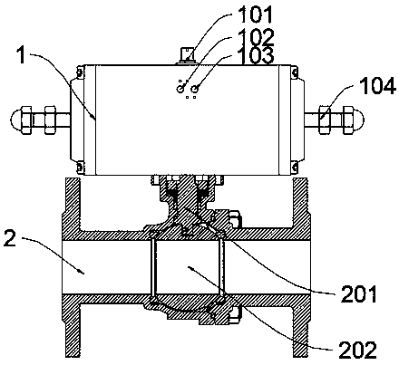
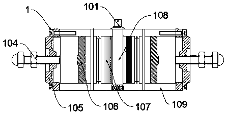
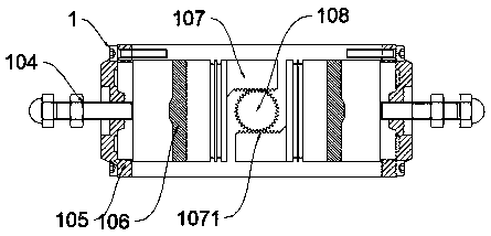
[0021] see Figure 1-4 , an embodiment provided by the present invention: a full-stroke adjustable pneumatic valve, including a pneumatic actuator 1, an extended limit adjustment screw 104 is installed in the middle of both sides of the pneumatic actuator 1, and the lengthened limit adjustment screw 104 is embedded in the pneumatic actuator 1 and fixed with the piston 106, the setting of the lengthened limit adjustment screw 104 can produce a certain displacement or rotation angle, that is, any angle between 0 degrees and 90 degrees, so as to achieve the required opening position of any angle, so that the channel inside The flow is controllable.

[0022] Further, th...


PUM


Abstract

The invention discloses a total-travel regulating pneumatic valve, relates to the field of pneumatic valves, and solves the problem that in the prior art, the travel of a pneumatic executing mechanismis adjusted only at two positions of 0 degree and 90 degrees. A lengthening and limiting regulating screw is mounted between the two sides of a pneumatic executing mechanism; the pneumatic executingmechanism comprises a cylinder block; a gear is mounted in the middle of the inner part of the cylinder block; saw-toothed thrust sliding blocks are correspondingly arranged on two sides of the gear;a piston is mounted on one side of each saw-toothed thrust sliding block; the saw-toothed thrust sliding blocks comprise sliding racks; an air inlet and an air outlet are formed in the middle of the upper end of the front end surface of the pneumatic executing mechanism; an output shaft is mounted in the middle of the upper end of the pneumatic executing mechanism; end covers are correspondingly mounted on two sides of the cylinder block; and a valve body is mounted at the lower end of the pneumatic executing mechanism, and comprises a valve rod and a valve ball.

Description

technical field [0001] The invention relates to the field of pneumatic valves, in particular to full-stroke adjustable pneumatic valves. Background technique [0002] Pneumatic valves are widely used in the field of industrial automation processes. Pneumatic valves are usually composed of a pneumatic actuator and a valve. The air source is used as power to connect the pneumatic actuator to drive the valve. Realize the switch and adjustment action of the valve, so as to achieve the purpose of switching or adjusting the flow direction of the pipeline medium. [0003] At present, the commonly used pneumatic valves often encounter a problem, that is, the stroke adjustment of the pneumatic actuator that controls the valve can only be adjusted at two positions of 0 degrees and 90 degrees, which is far from meeting the market demand; therefore, the market urgently needs to develop full stroke adjustment. Pneumatic valves to help people solve existing problems. Contents of the in...

Claims


Application Information

Patent Timeline
Patent Type & Authority Applications(China)
IPC IPC(8): F16K31/122F16K31/54F16K5/06
CPCF16K31/122F16K31/54F16K5/06
Inventor 夏克洲季善宏
Owner SHANGHAI JULIANG VALVE GRP CO LTD
Learn More