
Driving integrated circuit with fan-out line compensation design

A technology for driving integrated circuits and fan-out circuits, applied in nonlinear optics, instruments, optics, etc., can solve problems such as limited fan-out area space, unsatisfactory effects, and limited viewing area size

Inactive Publication Date: 2019-11-12
RAYDIUM SEMICON
View PDF13 Cites 2 Cited by
  • Summary
  • Abstract
  • Description
  • Claims
  • Application Information

AI Technical Summary

Problems solved by technology

However, adopting the above method will increase the area of ​​the peripheral area of ​​the display substrate, thereby limiting the size of the visible area
In addition, the space in the fan-out area is limited, resulting in the unsatisfactory effect of the existing method

Method used


Image

  • Driving integrated circuit with fan-out line compensation design
  • Driving integrated circuit with fan-out line compensation design
  • Driving integrated circuit with fan-out line compensation design

Examples


Embodiment Construction

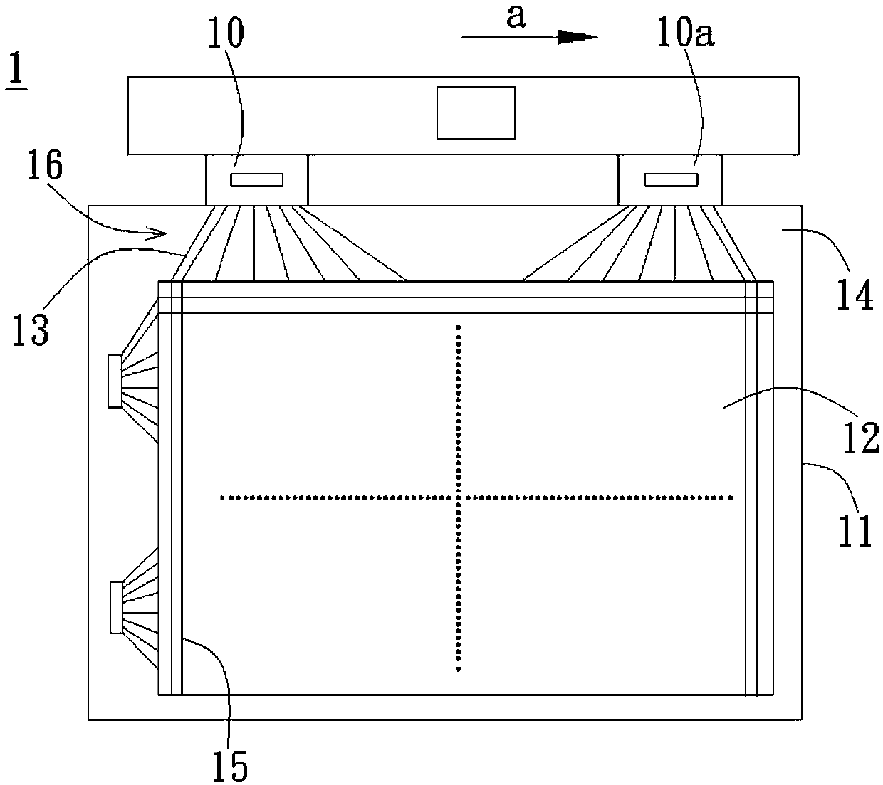
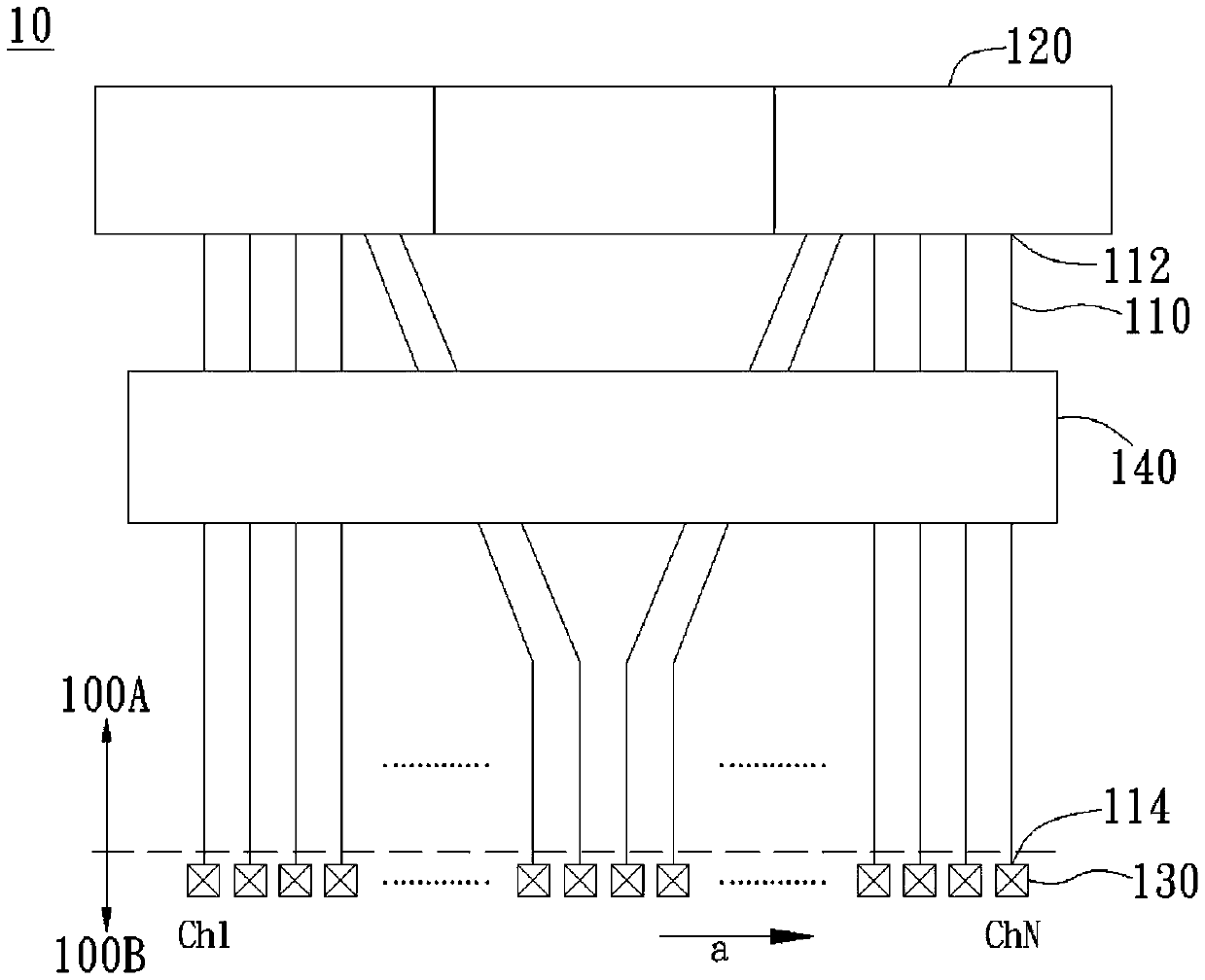
[0041] The invention provides a driving integrated circuit, which can be used in a display device. The display device is, for example, a liquid crystal display device. figure 1 is a schematic diagram of the display device 1 . Such as figure 1 As shown, the display device 1 has a first direction a parallel to one side of the display substrate 1. The display device 1 has a driving integrated circuit 10 and a driving integrated circuit 10a respectively arranged along a first direction a and located on one side of the display substrate 11. For example, the driver integrated circuit 10 and the driver integrated circuit 10 a are located outside the display substrate 11 . In other embodiments, the driver integrated circuit 10 and the driver integrated circuit 10a may be located on the display substrate 11 using a chip onglass (COG) technology. Each driving integrated circuit (10, 10a) is connected to a plurality of wires 15 in the display area 12 via the lines 13 located in the f...


PUM


Abstract

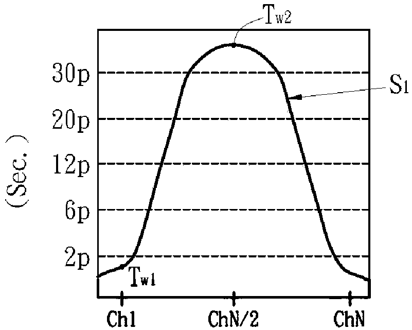
The invention relates to a driving integrated circuit with A fan-out line compensation design, and the circuit comprises a plurality of driving lines, a signal input unit and a compensation unit. Thedriving lines are arranged along a first direction. Each driving circuit is provided with an input end and an output end. The signal input unit is electrically connected with the input end and provides a driving signal. The plurality of connection pads are arranged corresponding to the driving circuit, and each connection pad is electrically connected with the output end. The compensation unit isarranged on the driving circuit. The driving signal is transmitted to the connecting pad through the compensation unit. The drive circuit has a time constant distribution in a first direction that varies in a first curve. The compensation unit has a second curve change based on the first curve, and the second curve and the first curve have opposite trend changes.

Description

technical field [0001] The present invention relates to driver integrated circuits; in particular, the present invention relates to driver integrated circuits for display devices. Background technique [0002] In a display device, a driving integrated circuit (such as a source driver) is connected to a wire (such as a data line) in the display substrate through a fan-out area formed around the display substrate. With the improvement of display quality, the number of wires in the display substrate also increases, which makes the distance between the central part and the edge part of each group of fan-out areas larger, and has different degrees of resistance-capacitance effects. This will affect the display quality. [0003] For the lines inside the driver integrated circuit, as the number of external (fan-out) lines increases, the number of lines inside the driver integrated circuit also increases, so that the internal lines also have different degrees of resistance-capacita...

Claims


Application Information

Patent Timeline
IPC IPC(8): G02F1/1345
CPCG02F1/13452
Inventor 任柏璋黄智全任致贤
Owner RAYDIUM SEMICON
Learn More