Fan-out wire structure, display panel and display device

A display panel and display device technology, applied in nonlinear optics, instruments, optics, etc.

Active Publication Date: 2018-12-21
CHONGQING HKC OPTOELECTRONICS TECH CO LTD +1
View PDF6 Cites 3 Cited by
  • Summary
  • Abstract
  • Description
  • Claims
  • Application Information

AI Technical Summary

Problems solved by technology

[0003] The main purpose of the present invention is to propose a fan-out wiring ...

Method used


Image

  • Fan-out wire structure, display panel and display device
  • Fan-out wire structure, display panel and display device
  • Fan-out wire structure, display panel and display device

Examples


Embodiment Construction

[0030] The following will clearly and completely describe the technical solutions in the embodiments of the present invention with reference to the accompanying drawings in the embodiments of the present invention. Obviously, the described embodiments are only part of the embodiments of the present invention, not all of them. Based on the embodiments of the present invention, all other embodiments obtained by persons of ordinary skill in the art without creative efforts fall within the protection scope of the present invention.

[0031] It should be noted that all directional indications (such as up, down, left, right, front, back...) in the embodiments of the present invention are only used to explain the relationship between the components in a certain posture (as shown in the accompanying drawings). Relative positional relationship, movement conditions, etc., if the specific posture changes, the directional indication will also change accordingly.

[0032] In the present in...


PUM


Abstract

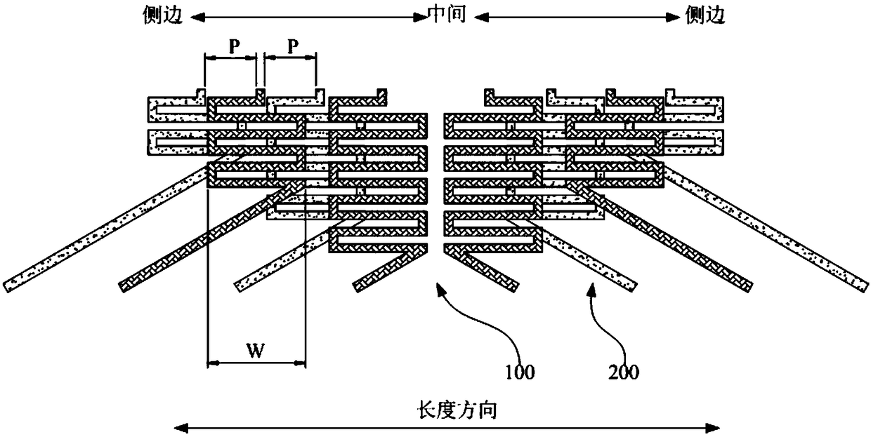
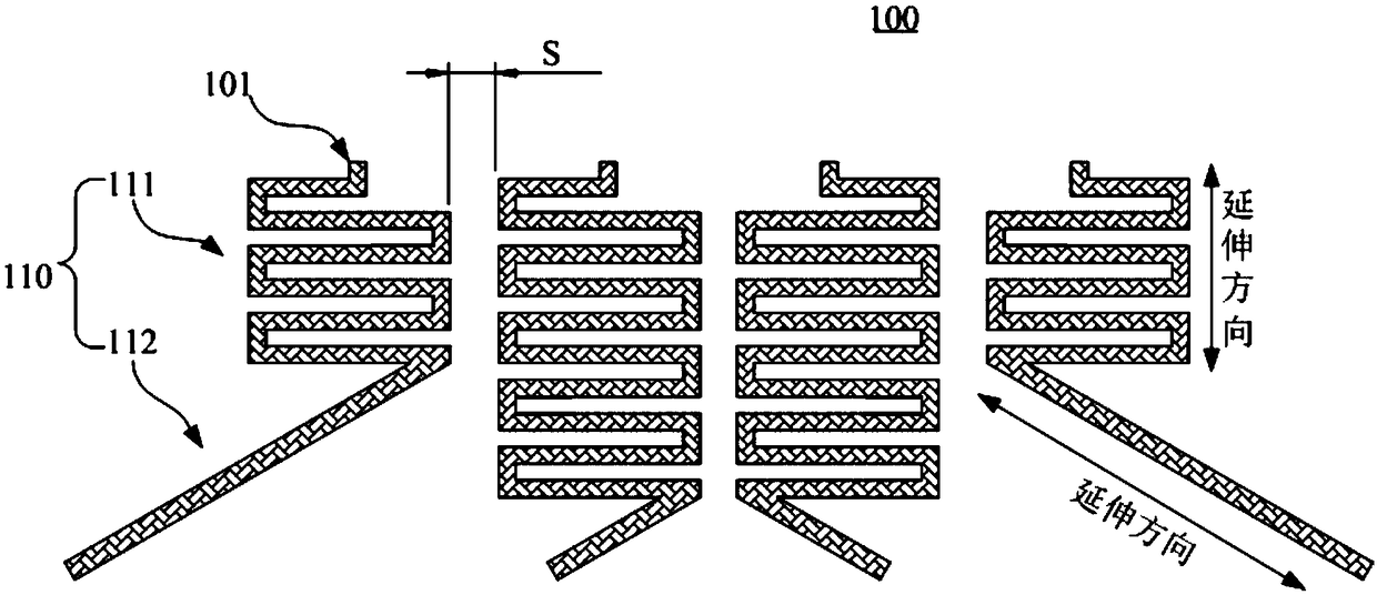
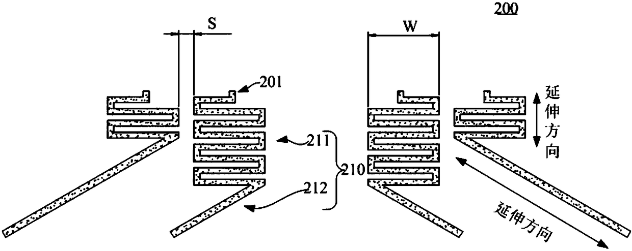
The invention discloses a fan-out wire structure, a display panel and a display device. The fan-out wire structure comprises a first fan-out layer, a second fan-out layer, and an insulating layer arranged between the first fan-out layer and the second fan-out layer; the first fan-out layer, the second fan-out layer and the insulating layer are arranged from top to bottom; the first fan-out layer comprises a plurality of first wires arranged at intervals; the second fan-out layer comprises a plurality of second wires arranged at intervals; the first wires and the second wires are alternately arranged; and the first wires and the second wires which are adjacent are partially overlapped. According to the technical scheme, the first fan-out layer and the second fan-out layer are arranged, andthe first wires and the second wires which are adjacent are partially overlapped and insulated mutually; and through the two-layer structure arrangement, when the space is compressed, the first wiresand the second wires have larger design space, so that the impedance difference of the wires is reduced.

Description

technical field [0001] The present invention relates to the field of display technology, in particular to a fan-out wiring structure, a display panel and a display device. Background technique [0002] The liquid crystal display panel includes an active area with multiple pixels and an external wire bonding area around the active area. The internal pixels of the panel are electrically connected to the driver chip in the external wire bonding area through the scanning line and the data line. There is a difference in the width of the data line or the scan line, and the part where the two lines are connected will form a fan-shaped wiring, that is, a fan-out wiring structure. The central part of the fan-out wiring structure is short and the side part is long, which makes the resistance values ​​of different lines different, resulting in differences in the incoming picture signals and affecting the display effect of the panel. At present, the purpose of equal impedance can be ac...

Claims


Application Information

Patent Timeline
IPC IPC(8): G02F1/1345
CPCG02F1/13452
Inventor 刘忠念
Owner CHONGQING HKC OPTOELECTRONICS TECH CO LTD
Why Eureka
Try Eureka