Al technical title is built by PatSnap Al team. It summarizes the technical point description of the patent document.
An overcurrent protection and relay technology, applied in the directions of relay ventilation/cooling/heating, relay terminal arrangement, etc., can solve the problems of loose cables, damage relays, and shorten the service life of relays, so as to facilitate wiring and movement, improve The effect of service life
Active Publication Date: 2021-07-09
BEIJING JINGYIBEIFANG INSTR
View PDF0 Cites 2 Cited by
Summary
Abstract
Description
Claims
Application Information
AI Technical Summary
This helps you quickly interpret patents by identifying the three key elements:
Problems solved by technology
Method used
Benefits of technology
Problems solved by technology
[0003] The existing relays are small in size and many electronic components are installed inside. Due to the compact installation structure, the electronic components are prone to heat in the working state. Generally, heat dissipation is only achieved by setting cooling holes on the relay housing. However, this type of relay only When the relay with cooling holes is working for a long time, its internal heat cannot be discharged in time. Because the heat cannot be removed in time, some parts will be damaged and the service life of the relay will be reduced. The existing relay is generally fixed and installed, which is inconvenient for wiring and Replacement, the general overcurrent protection relay is installed in the factory, it is easy to vibrate with the vibration of the machine in the factory, so that the cable connecting the relay will be loose and the electrical components inside the relay will be damaged
Method used
Image
Click on the blue label to locate the original text in one second.
Reading with bidirectional positioning of images and text.
Examples
Embodiment Construction
[0032] In order to make the purpose, features and advantages of the present invention more obvious and understandable, the technical solutions in the embodiments of the present invention will be clearly and completely described below in conjunction with the accompanying drawings in the embodiments of the present invention. Obviously, the following The described embodiments are only some, not all, embodiments of the present invention. Based on the embodiments of the present invention, all other embodiments obtained by persons of ordinary skill in the art without making creative efforts belong to the protection scope of the present invention.
[0033] The technical solutions of the present invention will be further described below in conjunction with the accompanying drawings and through specific implementation methods.
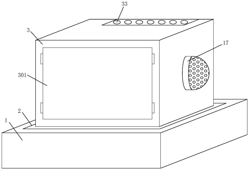
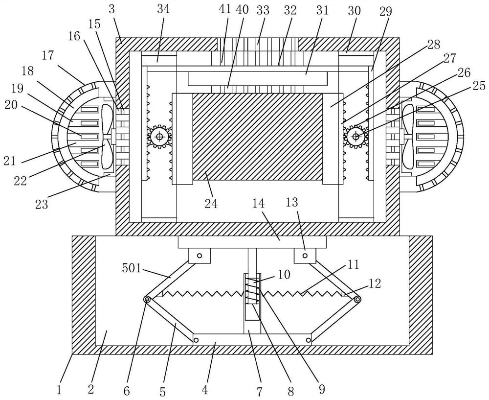
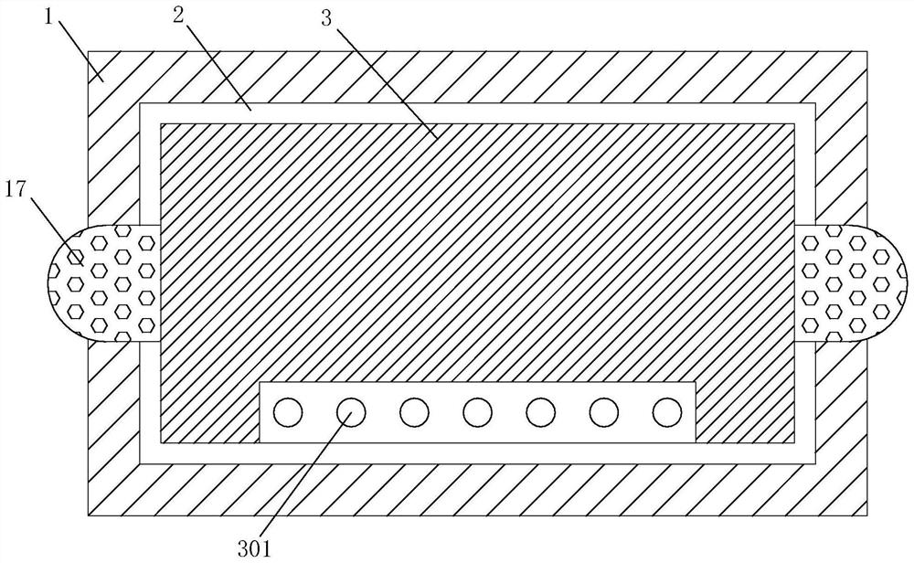
[0034] see Figure 1-6 As shown, an overcurrent protection relay includes a base 1, a vibration damping device, a heat dissipation device, a fixing device and...
PUM
Abstract
The invention belongs to the technical field of relays, specifically an overcurrent protection relay, including a base, a movable slot, a protective shell, a side door, a bottom plate, a first connecting rod, a second connecting rod, a connecting shaft, a fixed cylinder, a slider, The first spring, the connecting rod, the second spring, the connecting block, the fixing block, the fixing plate, the heat dissipation hole, the anti-dust net, the side cover, the ventilation groove, the refrigeration pipe, the semiconductor refrigeration sheet, the heat dissipation cavity, the fan, the mounting frame, and the relay body , micro motor, gear, first rack plate, mounting plate, second rack plate, side plate, movable plate, fixed rod, wire slot, through slot, pull rod, limit slot, third spring, fixed column, Card board, line board and card slot. The blower of the present invention drives the air to enter the ventilation slot from the air intake hole at one end of the side cover, and cools the air through the refrigeration pipe and the semiconductor cooling sheet in the ventilation slot to the inside of the protective case, thereby cooling the relay body when it is working. , improve the service life of the relay.
Description
technical field [0001] The invention belongs to the technical field of relays, in particular to an overcurrent protection relay. Background technique [0002] Overcurrent protection relay: the currently better overcurrent protection relay can integrate protection, single-phase current measurement, and control functions, and realize data sharing and remote control with the remote host through the in-com interface, and through the in-con interface Realize the data sharing and remote control functions with the remote host computer, focusing on its protection functions can be generally summarized as phase elements and grounding elements: inverse time overcurrent protection, short delay protection, overcurrent protection when instantaneous current transformer ratio, Overload alarm, zone interlock, and self-perfect self-test function ensure that the device provides reliable protection for primary equipment. [0003] The existing relays are small in size and many electronic compon...
Claims
Application Information
Patent Timeline
Application Date:The date an application was filed.
Publication Date:The date a patent or application was officially published.
First Publication Date:The earliest publication date of a patent with the same application number.
Issue Date:Publication date of the patent grant document.
PCT Entry Date:The Entry date of PCT National Phase.
Estimated Expiry Date:The statutory expiry date of a patent right according to the Patent Law, and it is the longest term of protection that the patent right can achieve without the termination of the patent right due to other reasons(Term extension factor has been taken into account ).
Invalid Date:Actual expiry date is based on effective date or publication date of legal transaction data of invalid patent.