
Novel short-range zinc liquid electroplating assembly line

An assembly line, short-range technology, applied in the electrolysis process, electrolysis components, cells, etc., can solve the problems of pipeline impact, limited positioning ability of the robotic arm, and heavy steel plate weight, and achieve the effect of shortening the time.

Active Publication Date: 2019-11-15
嘉兴市金鹰新材料股份有限公司
View PDF7 Cites 2 Cited by
  • Summary
  • Abstract
  • Description
  • Claims
  • Application Information

AI Technical Summary

Problems solved by technology

[0005] In order to solve the above technical problems, the present invention provides a new type of short-range zinc liquid electroplating line to solve the problem that the existing line can only transport the steel plate that has been electroplated or the steel plate that has not been electroplated, and the electroplating process requires additional precision assembly. The positioning robot arm is used to clamp the steel plate for electroplating operation. Due to the limited positioning ability of the robot arm, the requirements for the transmission interval and position of the steel plate on the conveyor belt are relatively strict, which need to be controlled within the effective error value, while manual handling There are manual errors in picking and conveying, and it is easy to appear that the force point of the mechanical arm is unbalanced, causing the steel plate to fall in mid-air, and the weight of the steel plate is relatively heavy. When it falls, it is easy to collide with the assembly line or the electroplating tank.

Method used


Image

  • Novel short-range zinc liquid electroplating assembly line
  • Novel short-range zinc liquid electroplating assembly line
  • Novel short-range zinc liquid electroplating assembly line

Examples


Embodiment

[0027] as attached figure 1 to attach Figure 7 Shown:

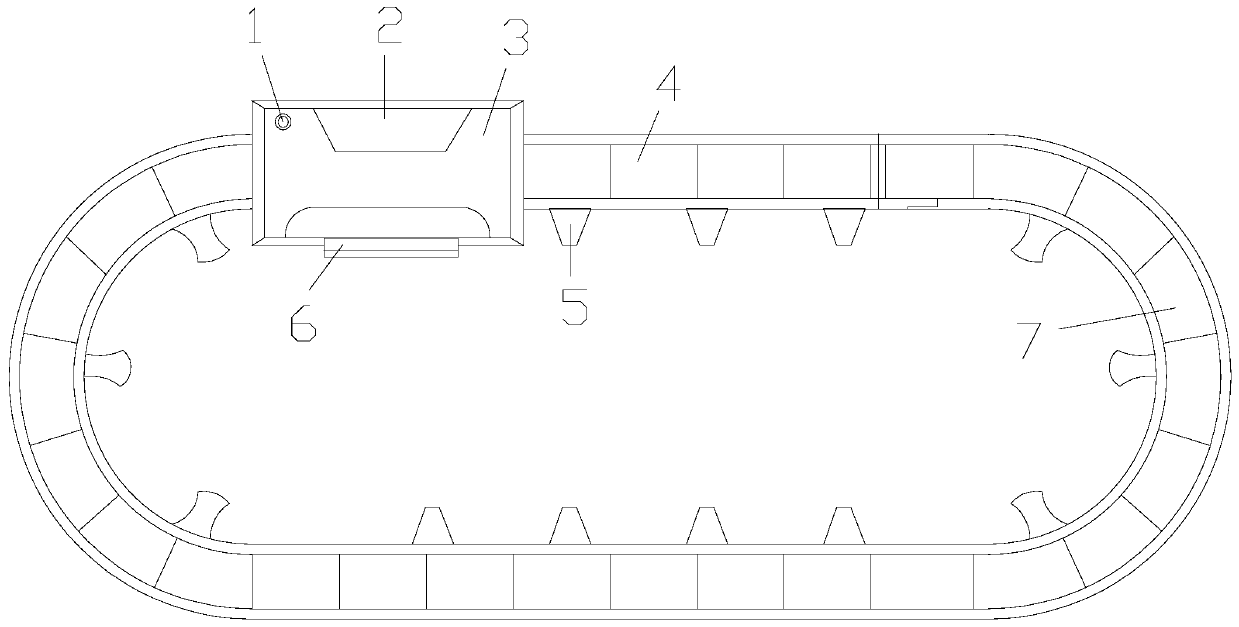
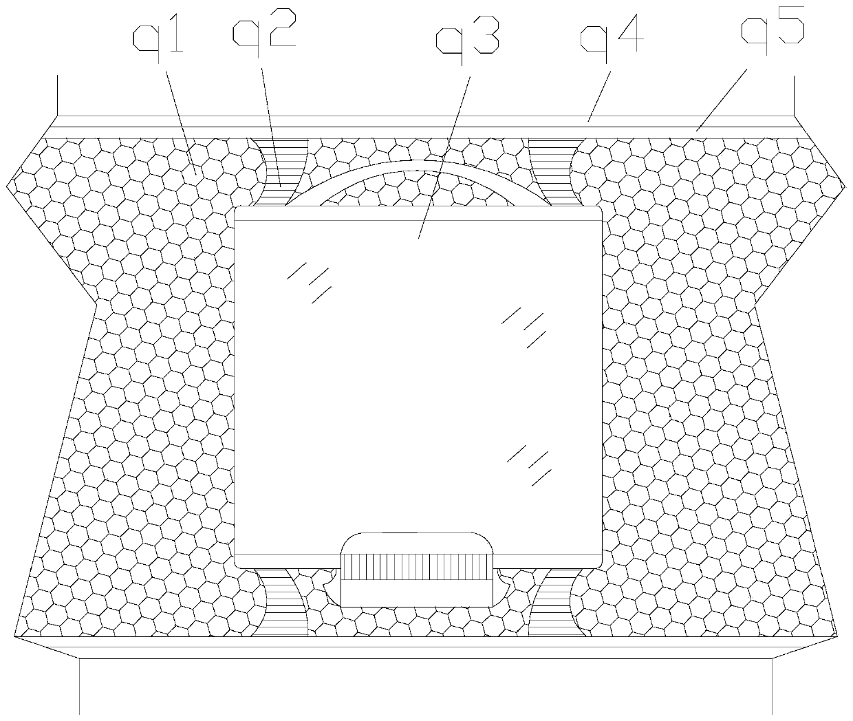
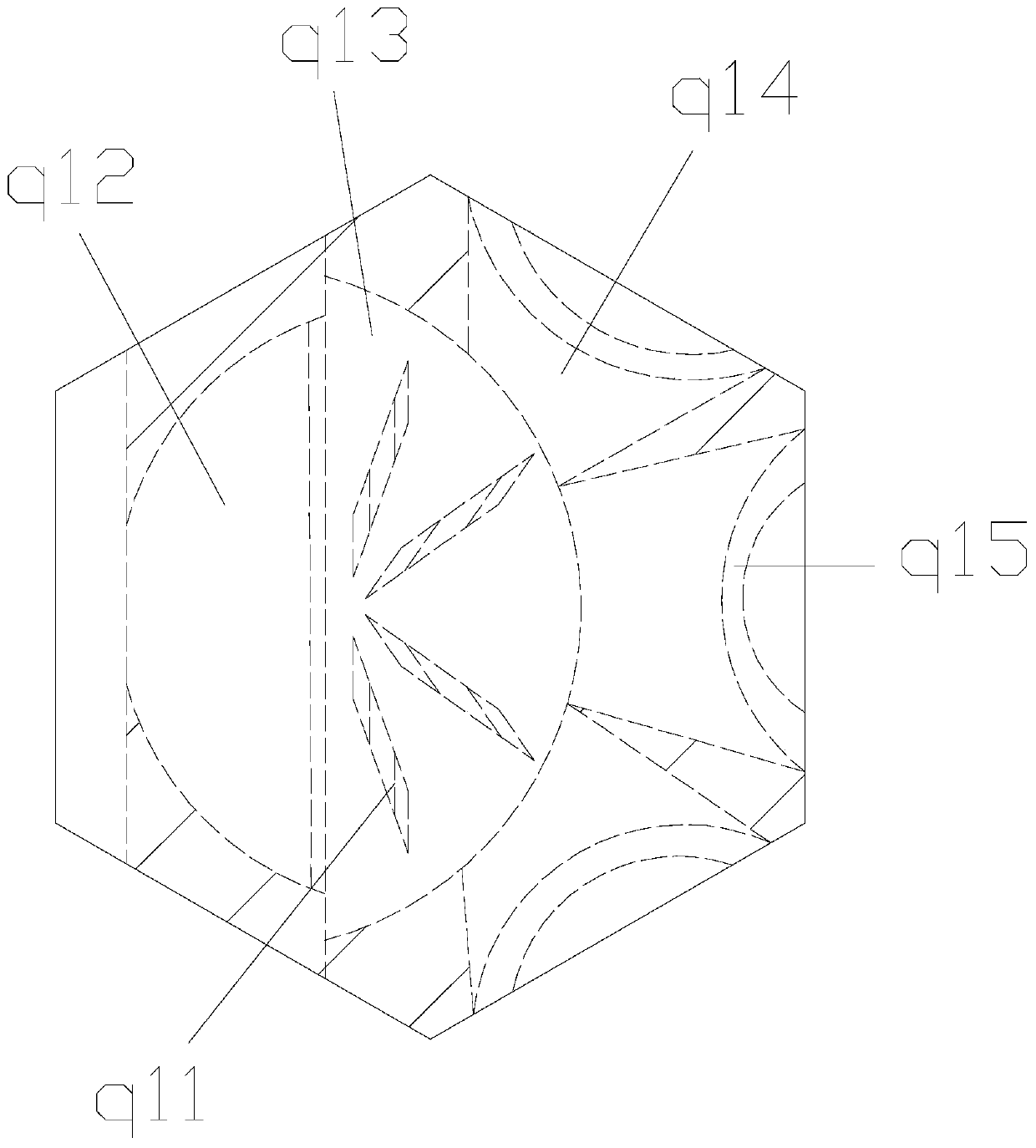
[0028] The invention provides a novel short-range zinc liquid electroplating line, the structure of which includes a fault alarm light 1, a flip side repair plate 2, a galvanized cover buckle 3, a short-range zinc liquid electroplating device 4, a support frame 5, an external power supply bar 6, and a row Transmission rack 7, the fault alarm lamp 1 is installed on the upper left end of the top surface of the galvanized cover buckle 3 by embedding, the back of the short-range zinc liquid electroplating device 4 is welded with the support frame 5, and the galvanized cover buckle 3 is There is an overturning side repair board 2, the external power strip 6 is installed inside the bottom of the galvanized cover buckle 3 by means of embedding, the back of the sub-row transmission frame 7 is welded to the support frame 5, and the short-range zinc solution electroplating The device 4 includes a plating solution guiding mechan...


PUM


Abstract

The invention provides a novel short-range zinc liquid electroplating assembly line. The novel short-range zinc liquid electroplating assembly line structurally comprises a fault warning lamp, a turning and side trimming plate, a zinc-plated cover buckle, a short-range zinc liquid electroplating device, support frames, an external power strip and a rowed conveying frame, wherein the fault warninglamp is mounted at the upper left end of the top end surface of the zinc-plated cover buckle in an embedded mode; and the back of the short-range zinc liquid electroplating device is welded to the support frames. The assembly line is capable of directly carrying out the electroplating process of a steel plate, loading the steel plate by using a steel plate short-range double-plating mechanism, pressing a plating liquid guiding and conveying mechanism by using the self weight of the steel plate under the assistance of the steel plate short-range double-plating mechanism, enabling the plating liquid guiding and conveying mechanism which is in a sealed state originally to open an external conveying opening, and forming a zinc protection layer on the surface of the steel plate; a transferringoperation of a mechanical arm can be directly replaced; the original weight of the steel plate is used as a power element in the process of the electroplating process; and the time needed by the electroplating process can be shortened.

Description

technical field [0001] The invention belongs to the field of electroplating processing of hardware, and more specifically relates to a novel short-range zinc liquid electroplating line. Background technique [0002] In the steel plate electroplating process, due to the limited zinc salt solution and electroplating tank, it is necessary to clamp the steel plate from the assembly line into the electroplating tank through the clamp arm, form an electro-galvanized layer on the surface of the steel plate through electrolysis, and then hang the plated steel plate clamp , placed on the assembly line, for subsequent transportation, and enters the next process. [0003] Based on the above description, the inventors found that the existing novel short-range zinc liquid electroplating line mainly has the following deficiencies, such as: [0004] Since the assembly line can only transport the steel plate that has been electroplated or the steel plate that has not been electroplated, th...

Claims


Application Information

Patent Timeline
IPC IPC(8): C25D17/28C25D3/22C25D7/00C25D21/14C25D19/00
CPCC25D3/22C25D7/00C25D17/28C25D21/14
Inventor 林玉芳
Owner 嘉兴市金鹰新材料股份有限公司
Learn More