
Stirring device for intermittent constant-velocity discharge and construction method for self-leveling floor

A mixing device and intermittent technology, applied in the field of rapid discharge mixing devices, can solve the problems of inconvenient control of equal discharge, insufficient uniformity, limited self-flow efficiency of concrete, etc.

Active Publication Date: 2020-12-11
福建磊鑫(集团)有限公司
View PDF5 Cites 0 Cited by
  • Summary
  • Abstract
  • Description
  • Claims
  • Application Information

AI Technical Summary

Problems solved by technology

[0004] In the existing technology, when a large area of ​​base is used for self-leveling floor construction, after a large amount of concrete is injected, due to the large coverage area, there are many internal stress problems, and a series of problems such as internal pores, collapse, and fracture are prone to occur after molding. In practical applications, in order to overcome the problems of limited self-flowing efficiency and insufficient uniformity of concrete in large-area construction, the construction base can be separated into areas of the same size, which can overcome the above problems and facilitate rapid construction. However, in the prior art , the device used for mixing concrete is not convenient to control the same amount of output when the material is discharged. If the output is measured every time, the processing efficiency is low

Method used


Image

  • Stirring device for intermittent constant-velocity discharge and construction method for self-leveling floor
  • Stirring device for intermittent constant-velocity discharge and construction method for self-leveling floor
  • Stirring device for intermittent constant-velocity discharge and construction method for self-leveling floor

Examples


Embodiment 1

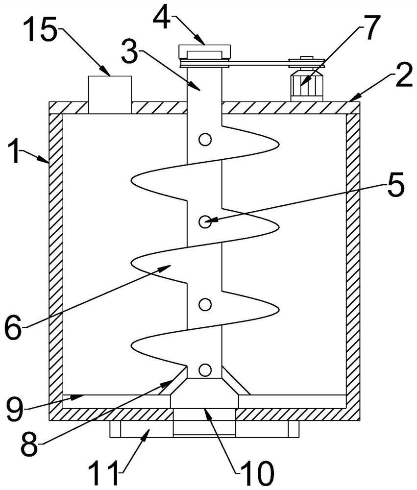
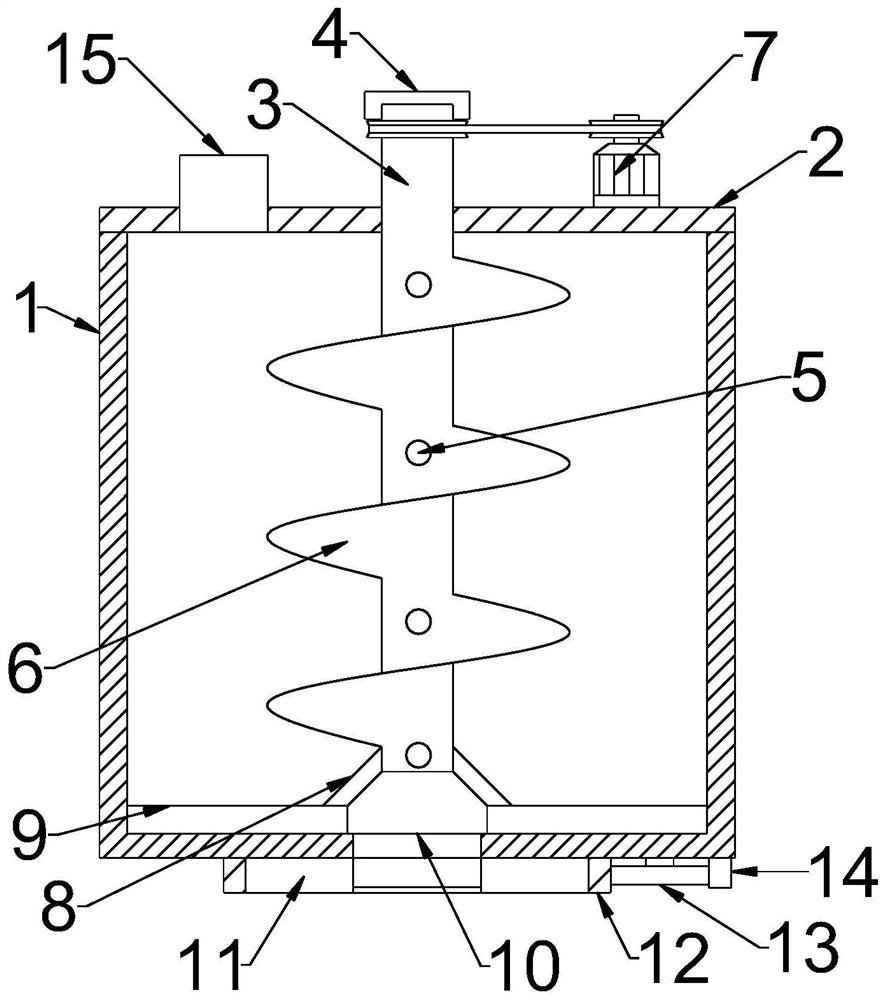
[0036] see figure 1 , in an embodiment of the present invention, a stirring device for intermittent constant-velocity discharge includes a kettle body structure composed of a housing 1 and an upper cover 2, the upper cover 2 is connected with a stirring mechanism, and the housing The lower end of the body 1 is provided with a discharge hole 10, and the stirring mechanism is composed of a rotating shaft 3 for introducing additives and connected with a spiral fan blade 6, and the upper end of the rotating shaft 3 is connected to a motor 7 for transmission.

[0037] The lower end of the housing 1 is located on the periphery of the discharge hole 10 and is connected with a discharge structure 11 . The discharge structure 11 has a valve mechanism for controlling the discharge hole 10 to discharge downward.

[0038] The upper end of the upper cover 2 is provided with a feed pipe 15 through which the material is put into the housing 1 through the feed pipe 15. The middle part of the ...

Embodiment 2

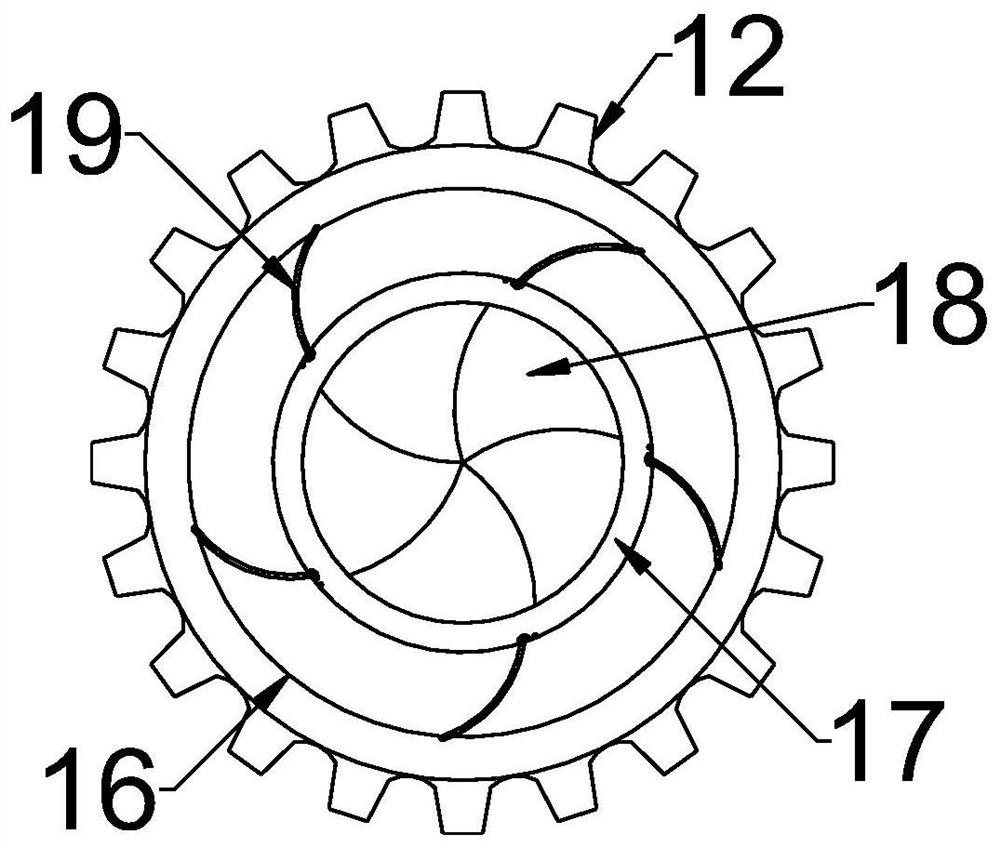
[0049] see Figure 2-6 , in the embodiment of the present invention, in practical application, in order to overcome the problem of limited self-flowing efficiency and insufficient uniformity of concrete in large-area construction, the construction base is usually separated, so that pumping construction is carried out on the separated independent small area, In order to achieve this effect, on the basis of Embodiment 1, a stirring device for intermittent constant-speed discharge, the discharge structure 11 is composed of an outer cylinder 16 that is rotatably connected to the bottom of the housing 1 and is riveted or welded. The inner cylinder 17 fixed on the bottom of the housing 1 is arranged concentrically. The outer cylinder 16 is located on the periphery of the inner cylinder 17. The inner cylinder 17 and the discharge hole 10 are arranged opposite and matched in size. The rotating connection is provided with five sets of discharge baffles 18 for controlling the discharge ...


PUM


Abstract

The invention discloses a batch-type uniform-speed discharging stirring device. The batch-type uniform-speed discharging stirring device comprises a kettle structure formed by assembling of a shell and an upper cover, the upper cover is provided with a stirring mechanism in a connected mode, a discharging hole is formed in the lower end of the shell in a penetrating mode, the stirring mechanism iscomposed of spiral fan blades connected to the periphery of a rotating shaft and used for introducing additives, the upper end of the rotating shaft is connected with a motor in a transmission mode,and a discharging mechanism opened in a mechanical and batch-type mode is further arranged at the lower end, of the periphery of the discharging hole, of the shell in a connected mode. A constructionmethod of a self-leveling terrace comprises the following steps that a base layer is checked, pulling-drawing detecting is conducted, and the base layer is cleaned; grinding, leveling by pushing and dust suction treatment are conducted; repairing treatment is conducted on gaps and hollowing parts; coating and painting of an interfacial agent are conducted, and line snapping and area division are conducted; mixed slurry is machined by using the device, and pumping construction is conducted after testing; and still standing and solidification, coating and painting of a protective agent, divisiondismantling and filling of joint mixture are conducted. The batch-type uniform-speed discharging stirring device can be matched with division-type construction to realize equal-amount batch-type material injection, and thus the structure problem of large-area construction is solved.

Description

technical field [0001] The invention relates to the technical field of construction of self-leveling floors, in particular to an intermittent constant-velocity discharging stirring device and a construction method for self-leveling floors. Background technique [0002] Self-leveling is a solvent-free, self-leveling, high-build epoxy floor coating with dense particles. Self-leveling solves the six major problems in floor installation. It is a ground construction technology. It is a liquid substance mixed with multiple materials and water. After being poured into the ground, this substance can flow along the ground according to the unevenness of the ground to automatically level the ground. [0003] The self-leveling floor engineering surface coating is beautiful, high cleanliness, high wear resistance and load-bearing, the most important thing is the beautiful decorative effect, because the first reaction of people's vision is the color and effect of the surface. [0004] I...

Claims


Application Information

Patent Timeline
Patent Type & Authority Patents(China)
IPC IPC(8): E04F21/24E04F15/12B28C5/16
CPCB28C5/16E04F15/12E04F21/24
Inventor 苏龙辉张金龙张晟王强吴浩顾劲松沈雪怡黄斌王汉东胡捷
Owner 福建磊鑫(集团)有限公司
Learn More