
Air conditioner

A technology of air conditioners and guide rails, which is applied to space heating and ventilation details, household heating, heating and ventilation hoods/covers, etc. It can solve the problems of poor appearance flatness and dust entry of air conditioners, so as to ensure the appearance and smoothness of the air conditioner degree, improve the effect of user experience

Active Publication Date: 2019-11-15
QINGDAO HAIER AIR CONDITIONER GENERAL CORP LTD +1
View PDF9 Cites 2 Cited by
  • Summary
  • Abstract
  • Description
  • Claims
  • Application Information

AI Technical Summary

Problems solved by technology

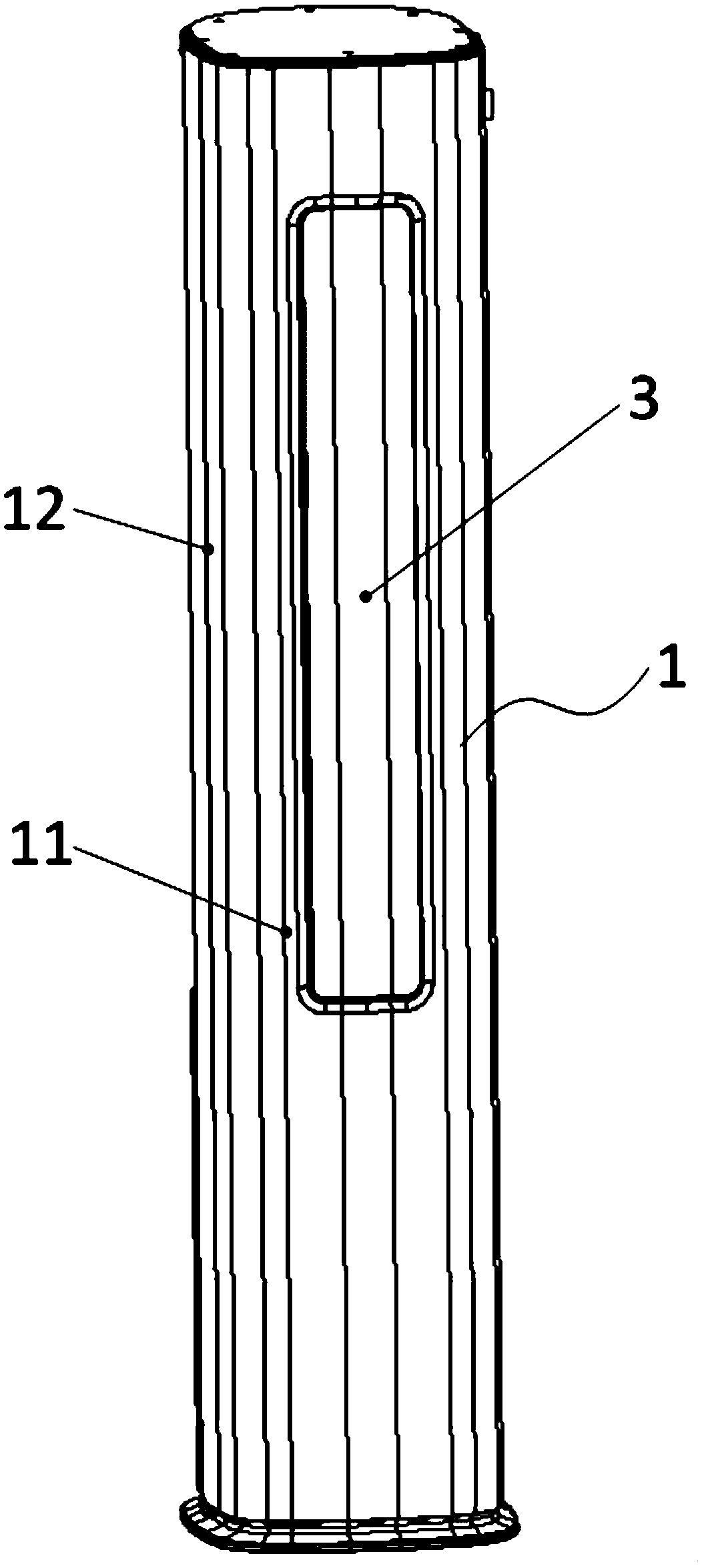
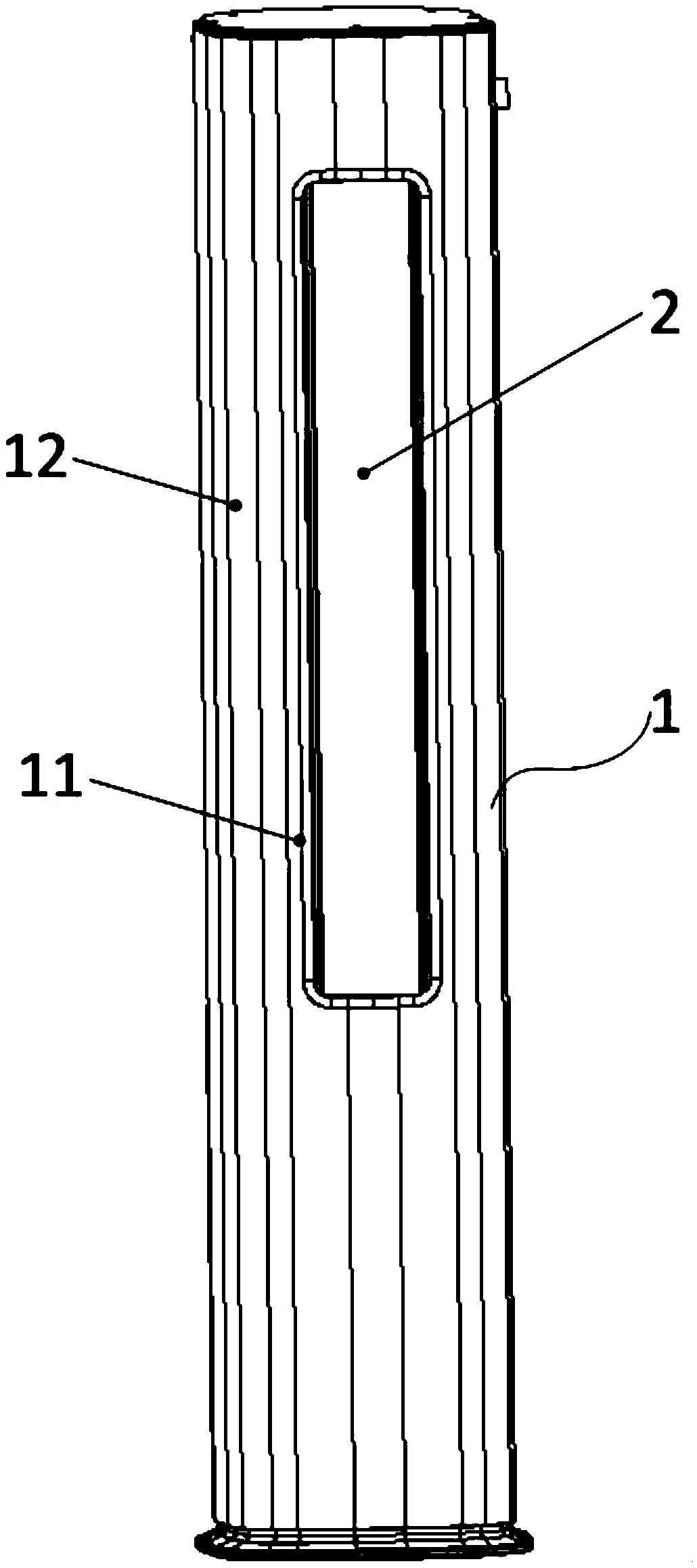
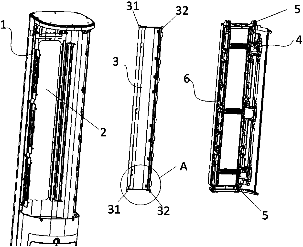
[0004] In order to solve the above-mentioned problems in the prior art, that is, the existing air conditioners have poor appearance flatness and dust easily enters the interior of the air conditioner through the gap between the door panel and the panel, the present invention provides an air conditioner, which includes a casing , the air outlet arranged on the front panel of the housing and the door panel capable of covering the air outlet, the air conditioner also includes a door panel movement mechanism, the door panel movement mechanism includes a drive transmission unit and a guide rail unit, and the guide rail The unit includes a first guide rail and a second guide rail, and the door panel is provided with a first sliding end and a second sliding end respectively slidably connected with the first guide rail and the second guide rail, so that the door panel can Driven by the driving transmission unit, the air outlet is opened or closed as the first sliding end and the second sliding end slide in the first guide rail and the second guide rail, and the first sliding end The first guide rail and the second guide rail are configured to make the door panel flush with the front panel when the air outlet is closed

Method used


Image

  • Air conditioner
  • Air conditioner
  • Air conditioner

Examples


Embodiment Construction

[0032] Preferred embodiments of the present invention are described below with reference to the accompanying drawings. Those skilled in the art should understand that these embodiments are only used to explain the technical principles of the present invention, and are not intended to limit the protection scope of the present invention. For example, although this embodiment is based on the attached figure 1 and figure 2 The cabinet-type air conditioner shown is described. The cabinet-type air conditioner is equipped with a door panel with an approximate planar structure. It can be understood that the shape of the door panel is designed according to the shape of the air conditioner and the shape of the air outlet. Obviously, the air conditioner of the present invention can also be equipped with other types of door panels according to specific requirements, such as the air conditioner of the present invention can also be a cabinet-type air conditioner equipped with curved door ...


PUM


Abstract

The invention relates to the technical field of air conditioners, in particular to an air conditioner. The air conditioner aims to solve the problem that an existing air conditioner is poor in appearance flatness, and dust can easily enter the air conditioner through a gap between a door sheet and a panel. The air conditioner comprises a shell, an air outlet, a door sheet and a door sheet movementmechanism, wherein the air outlet is formed in a front panel of the shell, and the door sheet can cover the air outlet; the door sheet movement mechanism comprises a drive transmission unit and a guide rail unit; and the guide rail unit comprises a first guide rail and a second guide rail. According to the air conditioner, the first guide rail and the second guide rail are configured to enable the door sheet to be flush with the front panel under the condition that the air outlet is closed, so that it is guaranteed that the door sheet and the front panel are closed seamlessly, in this case, the first guide rail and the second guide rail are arranged, so that the door sheet has a movement track capable of avoiding the position of the front panel so as to prevent the front panel from hindering the movement of the door sheet, and therefore normal opening and closing of the air outlet are guaranteed.

Description

technical field [0001] The invention relates to the technical field of air conditioners, in particular to an air conditioner. Background technique [0002] Air-conditioning cabinets are widely used in offices and family living rooms due to their large air volume and strong cooling and heating capabilities. Existing air-conditioning cabinets generally have such a structure: an air inlet and an air outlet are arranged on the casing of the air-conditioning cabinet, and a door panel is arranged on the air outlet. When the air outlet is not needed, the door panel is screwed out from the housing to cover the air outlet to prevent dust from entering. When the wind needs to be vented, the air deflector is retracted to open the air outlet to realize the venting to the indoor space. However, the existing wind deflectors use the center of the air conditioner cabinet as the center of the circle to perform a rotating movement to realize the opening and closing of the air outlet. In ord...

Claims


Application Information

Patent Timeline
Patent Type & Authority Applications(China)
IPC IPC(8): F24F13/20F24F13/24
CPCF24F13/20F24F13/24F24F2013/247Y02B30/70
Inventor 孟相宏田梦然
Owner QINGDAO HAIER AIR CONDITIONER GENERAL CORP LTD
Learn More