Automobile part surface defect detection device and detection method thereof
A surface defect detection device technology, applied in the direction of measuring devices, optical testing of defects/defects, material analysis through optical means, etc., can solve problems such as poor detection effect and scratched products entering the market, so as to reduce the risk of scratched workpieces Outflow, easy to zoom in and observe, and improve the effect of detection quality
- Summary
- Abstract
- Description
- Claims
- Application Information
AI Technical Summary
Problems solved by technology
Method used
Image
Examples
Embodiment 1
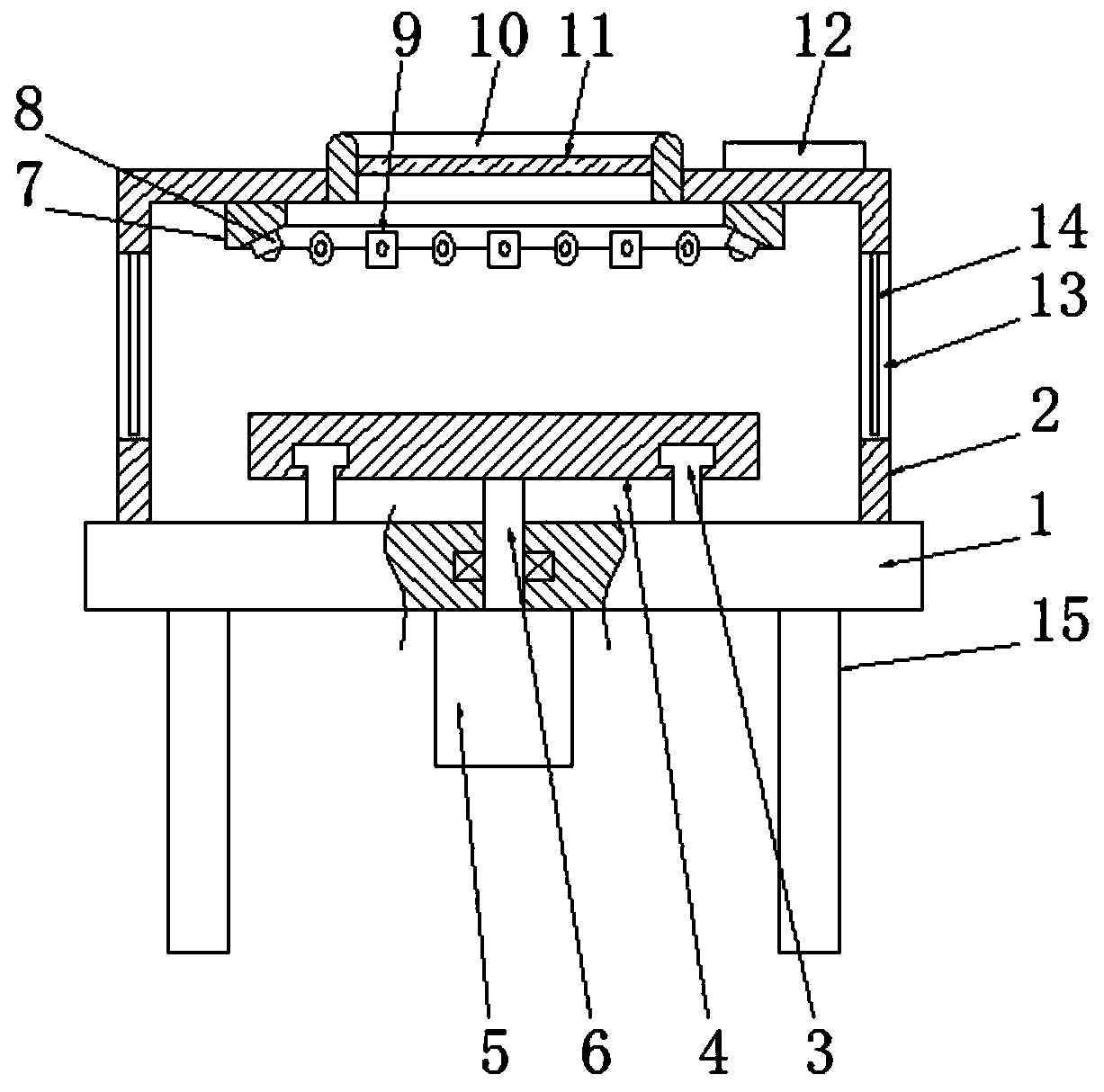
[0031] See figure 1, a surface defect detection device for auto parts includes a base 1, the bottom of the base 1 is evenly provided with a number of legs 15, the center of the bottom of the base 1 is fixedly connected to a motor 5, and the top of the base 1 is fixedly installed with a slide rail 3. The slide rail 3 is a ring structure, the slide rail 3 is rotatably connected with a detection platform 4, the bottom end of the detection platform 4 is fixedly connected with a rotating shaft 6, and the bottom end of the rotating shaft 6 runs through the base 1 and is rotatably connected On the motor 5, the axis of the rotating shaft 6 coincides with the axis of the detection platform 4, and the top of the base 1 is also fixedly connected with a dark box 2, and the dark box 2 is sleeved on the outside of the detection platform 4, and the top of the dark box 2 is embedded with a Observation window 10, the inner cavity of described observation window 10 is equipped with protective p...
Embodiment 2
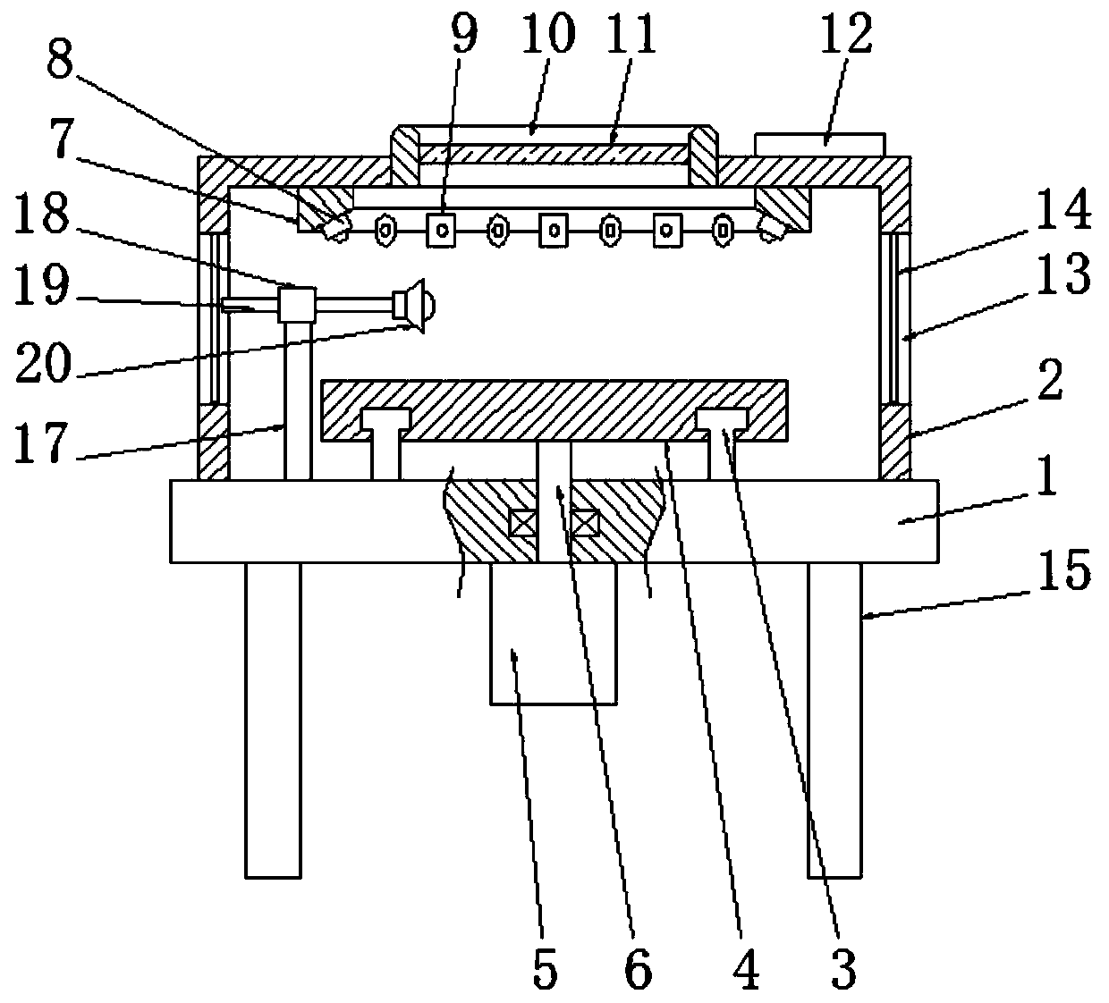
[0034] See figure 2 , and the difference from Embodiment 1 is that: the top side of the base 1 is fixedly installed with a vertical rod 17 matched with the detection table 4, the vertical rod 17 is located inside the dark box 2, and the top of the vertical rod 17 is connected to the There is a swivel base 18, and an extension rod 19 is embedded on the swivel base 18. There is a sliding connection between the swivel base 18 and the extension rod 19. The end of the extension rod 19 close to the detection table 4 is fixedly connected with a fixed-point lamp 20. The swivel base 18 can drive the extension rod 19 to rotate, thereby adjusting the lighting angle of the fixed-point lamp 20. At the same time, the extension rod 19 pushes and pulls back and forth on the swivel base 18 to adjust the position of the fixed-point lamp 20 on the detection table 4, and then adjust the fixed-point lamp 20. The specific lighting position enables fixed-point observation of the workpiece, which ca...
Embodiment 3
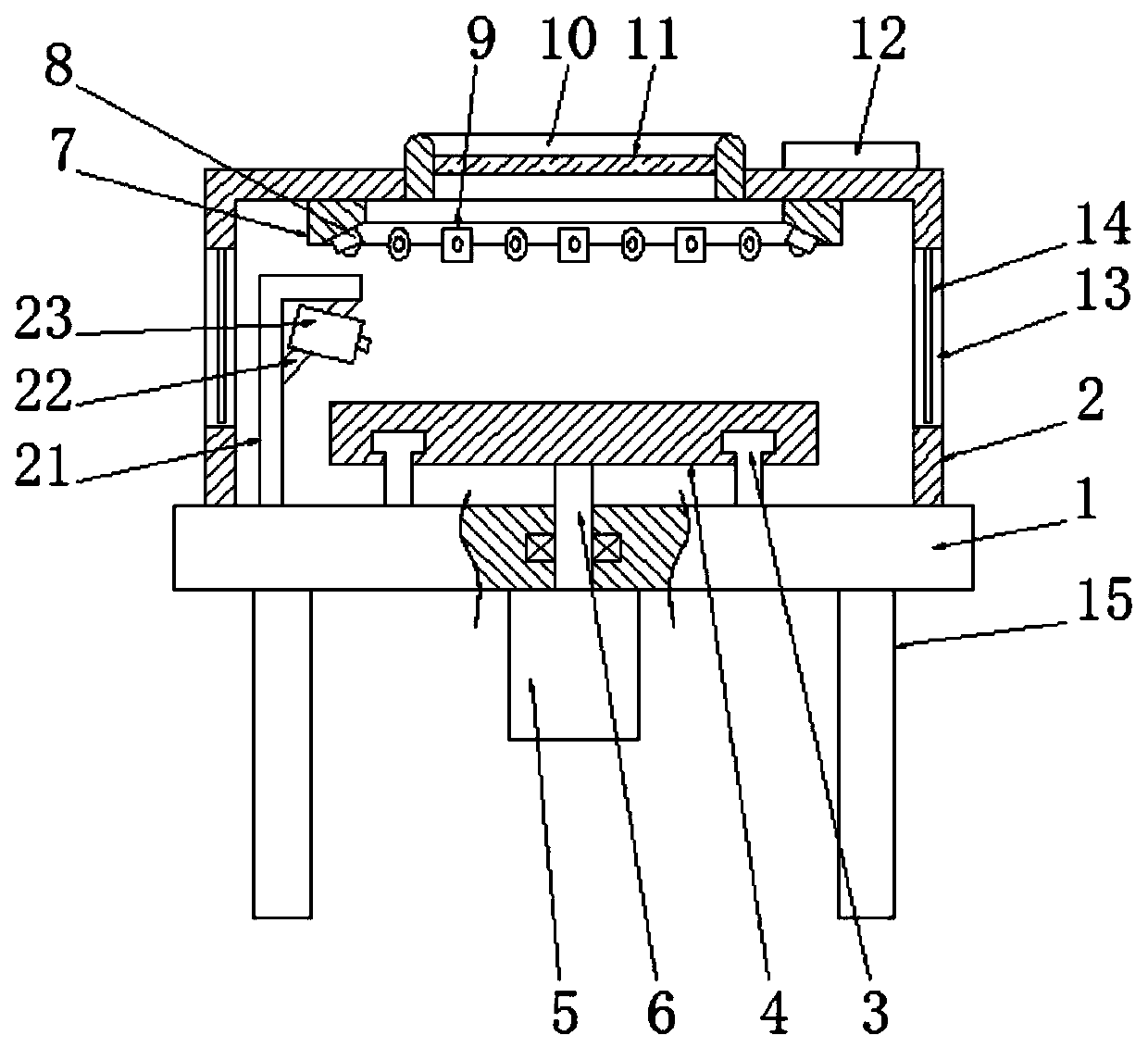
[0036] See image 3 The difference from Embodiment 1 is that: the top of the base 1 is also fixedly connected with a stand 21 that matches the detection platform 4, the stand 21 is an L-shaped structure, and the inner cavity of the stand 21 is fixedly installed with Fixed plate 22, described fixed plate 22 is inclined setting, is embedded with spray device 23 on the fixed plate 22, sprays the workpiece on the detection table 4 by spray device 23, makes the workpiece performance to be attached with a large amount of tiny water droplets, Then, the camera 9 is used to take pictures, which is convenient for later workers to carry out comparative observation, so as to find small scratches on the surface of the workpiece, thereby further improving the detection quality of the workpiece.
PUM
 Abstract
Description
Claims
Application Information
 - R&D
- Intellectual Property
- Life Sciences
- Materials
- Tech Scout
- Unparalleled Data Quality
- Higher Quality Content
- 60% Fewer Hallucinations
Browse by: Latest US Patents, China's latest patents, Technical Efficacy Thesaurus, Application Domain, Technology Topic, Popular Technical Reports.
© 2025 PatSnap. All rights reserved.Legal|Privacy policy|Modern Slavery Act Transparency Statement|Sitemap|About US| Contact US: help@patsnap.com


