Phase noise compensation device and method, receiver
A phase noise compensation and phase noise technology, which is applied in the field of phase noise compensation devices and methods, and receivers, can solve problems such as phase noise sensitivity, and achieve the effect of accurately estimating phase noise and ensuring transmission efficiency and performance
- Summary
- Abstract
- Description
- Claims
- Application Information
AI Technical Summary
Problems solved by technology
Method used
Image

Examples
Embodiment 1
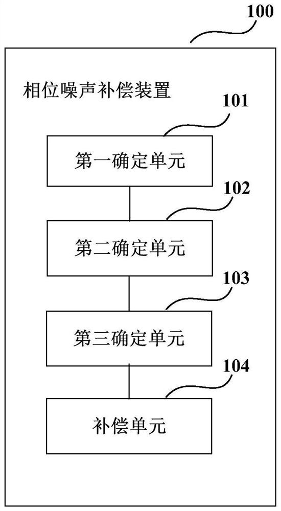
[0026] a first determining unit 101, which is used to determine the estimated value of the imperfection parameter of the transmitter according to the received signal;
[0031] In this embodiment, for example, the imperfection parameters of the transmitter include at least one of the following:
[0033] In this embodiment, because the transmitter is not ideal, the parameters remain relatively stable for a certain period of time, for example, several seconds
[0039]
[0042]
[0045] In this embodiment, the training sequence signal inserted into the transmission signal of the transmitter may be continuously inserted,
[0046] For example, the training sequence signal inserted into the transmitted signal can be expressed as:
[0050]
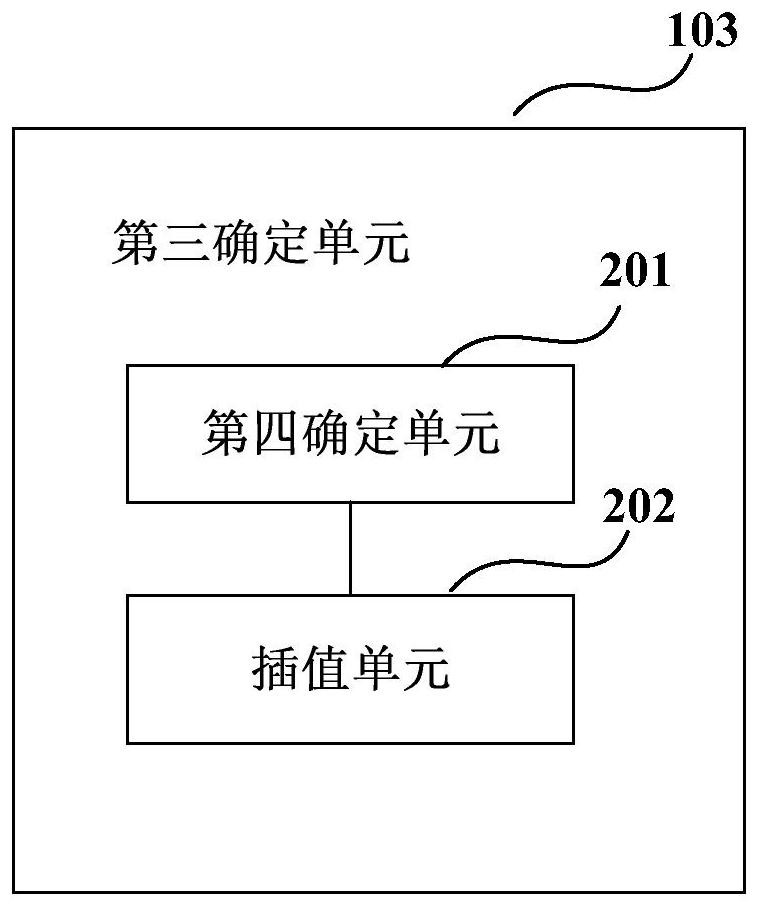
[0052] In this embodiment, the third determining unit 103 determines the phase noise of the received signal according to the correction signal. by
[0053] FIG. 2 is a schematic diagram of the third determining unit 103 in Embodiment 1 of the present ...
Embodiment 2
[0071] FIG. 5 is a schematic block diagram of a system configuration of a receiver according to Embodiment 2 of the present invention. As shown in FIG. 5, receiver 500
[0074] As shown in FIG. 5, after the received signal is processed by the equalization unit 501 and the frequency offset compensation unit 502, the received signal is processed by the phase noise
Embodiment 3
[0079] FIG. 6 is a schematic diagram of a phase noise compensation method according to Embodiment 3 of the present invention. As shown in Figure 6, the method includes:
[0080] Step 601: Determine the estimated value of the imperfection parameter of the transmitter according to the received signal;
[0083] Step 604: Perform phase noise compensation on the received signal according to the phase noise of the received signal.
[0084] FIG. 7 is another schematic diagram of a phase noise compensation method according to Embodiment 3 of the present invention. As shown in Figure 7, the method package
[0086] Step 702: Determine the estimated value of the imperfection parameter of the transmitter according to the received signal;
[0090] Step 706: Perform phase noise compensation on the received signal according to the phase noise of the received signal at all times.
[0094] The method for performing damage monitoring in a phase noise compensation device or receiver described in co...
PUM
 Abstract
Description
Claims
Application Information
 - R&D Engineer
- R&D Manager
- IP Professional
- Industry Leading Data Capabilities
- Powerful AI technology
- Patent DNA Extraction
Browse by: Latest US Patents, China's latest patents, Technical Efficacy Thesaurus, Application Domain, Technology Topic.
© 2024 PatSnap. All rights reserved.Legal|Privacy policy|Modern Slavery Act Transparency Statement|Sitemap