
Ejector pin arrangement equipment, method, and device

A technology of ejector and thimble, applied in the direction of electrical components, electrical components, etc., can solve the problems of poor accuracy and low efficiency, and achieve the effects of improving work efficiency, reducing costs, and eliminating quality risks

Inactive Publication Date: 2019-11-15
HITACHI BUILDING TECH GUANGZHOU CO LTD
View PDF5 Cites 0 Cited by
  • Summary
  • Abstract
  • Description
  • Claims
  • Application Information

AI Technical Summary

Problems solved by technology

[0003] In the process of implementation, the inventor found that there are at least the following problems in the traditional technology: to replace different types of PCB boards, it is necessary to readjust the position of the thimble, low efficiency and poor accuracy

Method used


Image

  • Ejector pin arrangement equipment, method, and device
  • Ejector pin arrangement equipment, method, and device
  • Ejector pin arrangement equipment, method, and device

Examples


Embodiment Construction

[0043] In order to facilitate the understanding of the present application, the present application will be described more fully below with reference to the relevant drawings. A preferred embodiment of the application is shown in the drawings. However, the present application can be embodied in many different forms and is not limited to the embodiments described herein. On the contrary, the purpose of providing these embodiments is to make the disclosure of this application more thorough and comprehensive.

[0044] It should be noted that when an element is considered to be "connected" to another element, it may be directly connected to and integrally integrated with the other element, or there may be an intervening element at the same time. The terms "collect", "parse", "indicate" and similar expressions are used herein for the purpose of description only.

[0045] Unless otherwise defined, all technical and scientific terms used herein have the same meaning as commonly und...


PUM


Abstract

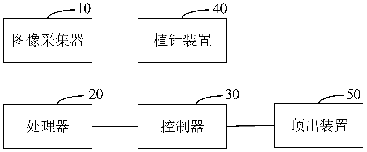
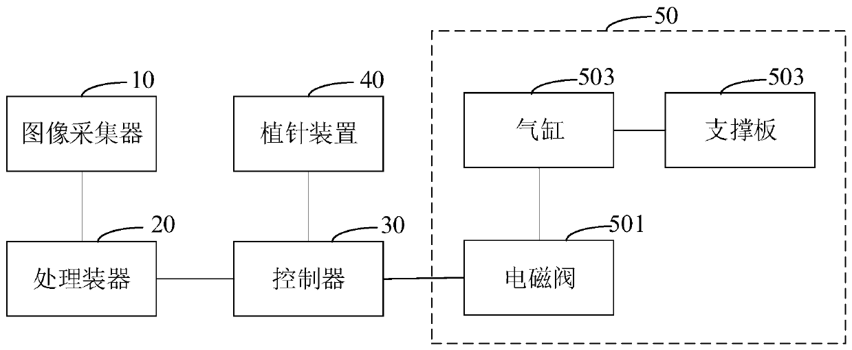
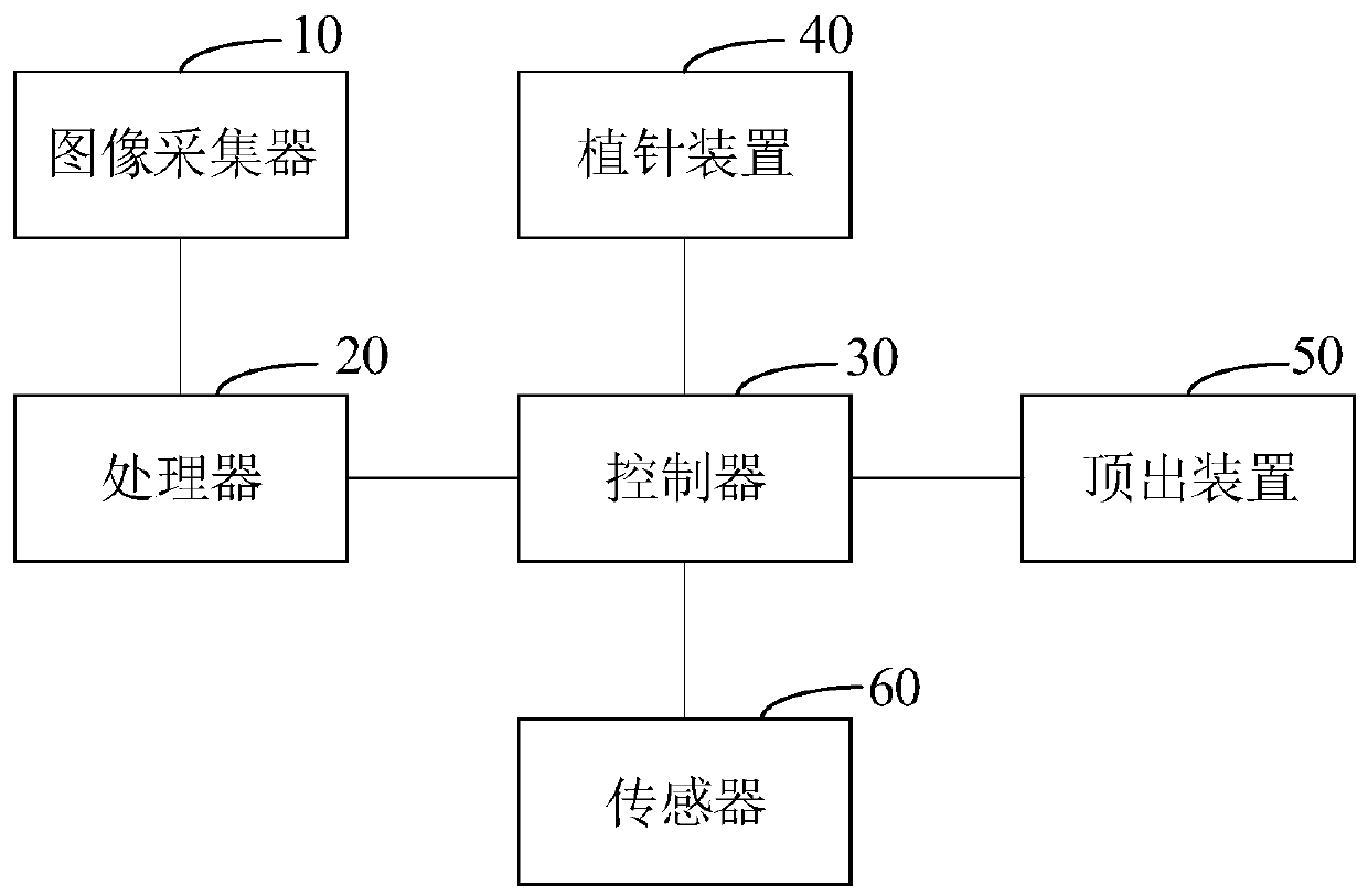
This application relates to ejector pin arrangement equipment, method, and device. The ejector pin arrangement equipment includes an image acquisition device, a processor, a controller, a pin implanting device and an ejection device, wherein the image acquisition device is connected with the processor; the controller is connected with the processor, the pin implanting device and the ejection device respectively; the image acquisition device is used for performing image acquisition on a PCB at a board stopping position on a conveying belt and transmitting the acquired image information to the processor; the processor analyzes the image information to obtain a target position, and the target position is transmitted to the controller; the controller indicates the pin implanting device to place the ejector pin at the corresponding position on the ejection device according to the target position; and after the pin implanting device is detected to complete ejector pin placement, the controller indicates the ejection device to act until the ejector pin contacts the PCB. Through the ejector pin arrangement equipment provided in the invention, the ejector pin arrangement position can be accurately positioned, the actual of manually arranging an ejector pin is replaced, and the overall work efficiency is improved.

Description

technical field [0001] The present application relates to the technical field of placement machines, in particular to a thimble arrangement device, method and device. Background technique [0002] When the placement machine is used to mount components on a daily basis, the PCB (Printed Circuit Board, printed circuit board) transfer device transfers the PCB board to a predetermined position, and the clamping device device installs the corresponding electronic components to the specified position on the PCB board according to the instructions. Location. During the installation process of the clamping component device to the PCB board, in order to prevent the deformation of the PCB board, thimble pins are usually placed at the bottom of the PCB board. The position of the thimble pins must avoid the position of the circuit and electronic components on the PCB board. At present, the supporting thimbles of most PCB processing and manufacturing plants or equipment manufacturing pl...

Claims


Application Information

Patent Timeline
Patent Type & Authority Applications(China)
IPC IPC(8): H05K13/00
CPCH05K13/0061
Inventor 肖朝根刘永新
Owner HITACHI BUILDING TECH GUANGZHOU CO LTD
Learn More