
Electric propulsion rescue boat

A technology for electric propulsion and rescue ship, applied in the field of ships

Active Publication Date: 2019-11-19
SHANGHAI MERCHANT SHIP DESIGN & RES INST
View PDF5 Cites 0 Cited by
  • Summary
  • Abstract
  • Description
  • Claims
  • Application Information

AI Technical Summary

Problems solved by technology

[0007] The purpose of the present invention is to provide an electric propulsion rescue ship to solve the technical problem of how to install a highly safe oil slick recovery system in the electric propulsion rescue ship

Method used


Image

  • Electric propulsion rescue boat
  • Electric propulsion rescue boat
  • Electric propulsion rescue boat

Examples


Embodiment Construction

[0027] The technical solutions of the present invention will be clearly and completely described below in conjunction with the embodiments. Obviously, the described embodiments are part of the embodiments of the present invention, but not all of them. Based on the embodiments of the present invention, all other embodiments obtained by persons of ordinary skill in the art without making creative efforts belong to the protection scope of the present invention.

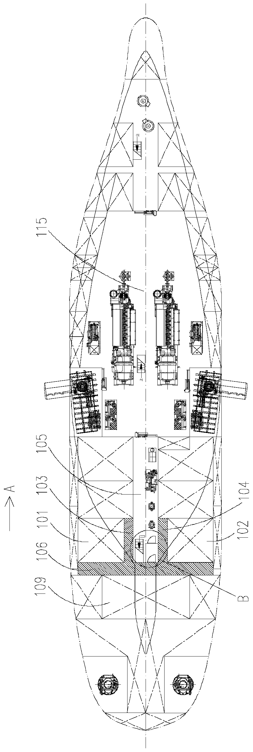
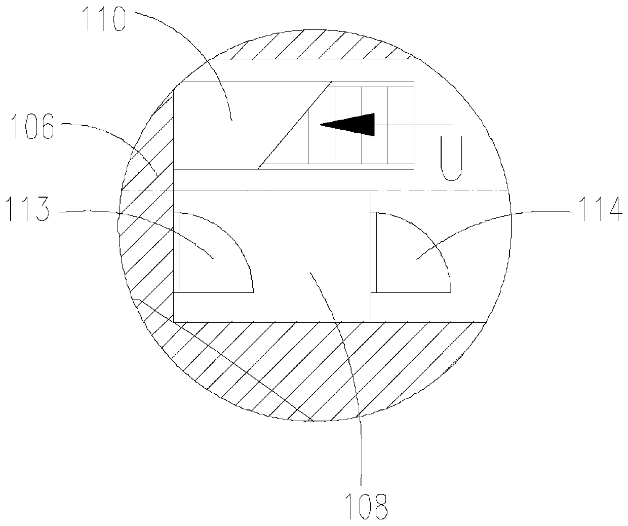
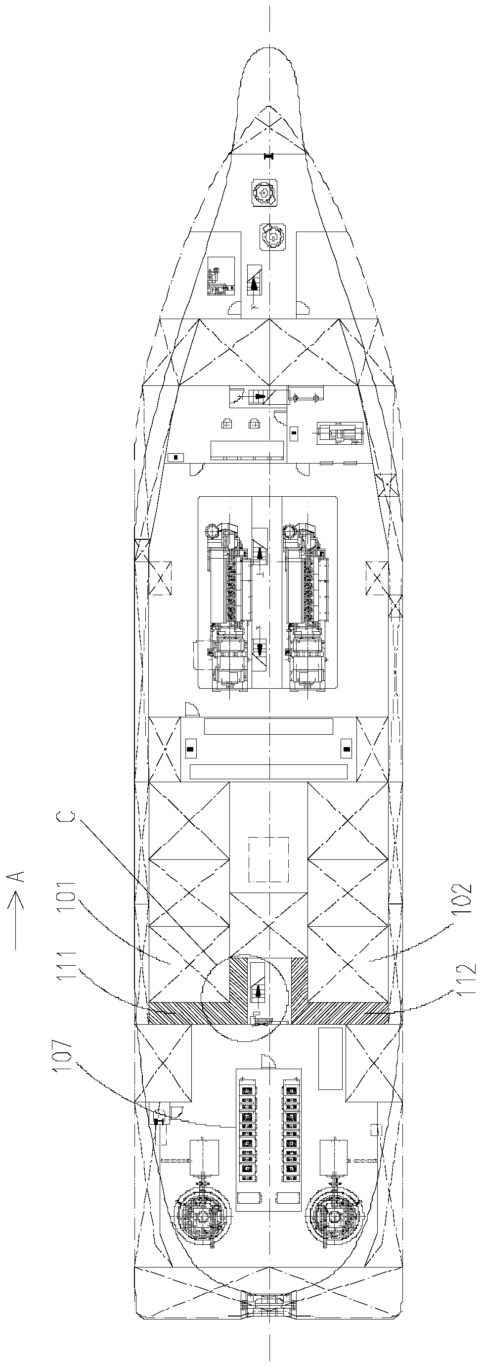
[0028] see Figure 1 to Figure 4 As shown, the present embodiment provides an electric propulsion rescue ship, including an oil slick recovery system and a pump room 105; The oil recovery cabin 101 and the starboard side oil slick recovery cabin 102 are arranged on both sides of the pump room 105; Between the cabins 101, and the first cabin body 103 is adjacent to the port oil slick recovery cabin 101; the second cabin body 104 is located between the pump room 105 and the starboard oil slick recovery cabin 102, and the ...


PUM


Abstract

The invention relates to the technical field of ships, in particular to an electric propulsion rescue boat. The electric propulsion rescue boat comprises a floating oil recovery system and a pump cabin. The floating oil recovery system comprises a left-side floating oil recovery cabin, a right-side floating oil recovery cabin and an isolation empty cabin. The left-side floating oil recovery cabinand the right-side floating oil recovery cabin are arranged on the two sides of the pump cabin. The isolation empty cabin comprises a first cabin body and a second cabin body. The first cabin body islocated between the pump cabin and the left-side floating oil recovery cabin and is adjacent to the left-side floating oil recovery cabin. The second cabin body is positioned between the pump cabin and the right-side floating oil recovery cabin and adjacent to the right-side floating oil recovery cabin. Combustible gas leakage sources in the left-side floating oil recovery cabin and the right-sidefloating oil recovery cabin are arranged in the first cabin body and the second cabin body. By arranging the first cabin body and the second cabin body, the left-side floating oil recovery cabin andthe right-side floating oil recovery cabin are not directly adjacent to the pump cabin, and combustible gas cannot leak to the non-dangerous areas, so that the safety is improved.

Description

technical field [0001] The invention relates to the technical field of ships, in particular to an electric propulsion rescue ship. Background technique [0002] At present, the common rescue ships or oil slick recovery ships with oil slick recovery systems are mainly propelled by conventional shafting. There are two shaft tunnels on both sides, and oil slick recovery system is arranged on the outside of the shaft tunnel or between the two shaft tunnels. [0003] According to the definition of hazardous area in the International Electrotechnical Commission standard, due to operational reasons, such as the leakage of piping and accessories, the area where flammable gas exists is a Class 1 hazardous area, for example, equipped with recovery oil delivery equipment (pump set) or piping systems and other areas with sources of flammable gas leakage. Non-hazardous areas are areas where explosive gas-air mixtures are unlikely and therefore no special precautions need to be taken in...

Claims


Application Information

Patent Timeline
IPC IPC(8): B63B11/00E02B15/04B63J2/02B63B35/32
CPCB63B11/00B63B35/32B63J2/02E02B15/046Y02A20/204
Inventor 杜鹏飞谢智康张毅史恭乾肖松张二敏许晶
Owner SHANGHAI MERCHANT SHIP DESIGN & RES INST
Learn More