Laser emitting device for three-dimensional positioning

A technology of laser emission and three-dimensional positioning, which is applied in the direction of using optical devices, active optical measuring devices, measuring devices, etc., which can solve the problems of limiting positioning accuracy and the inability of laser rotors to handle small high-frequency oscillations

Pending Publication Date: 2019-11-19
NANJING ENIGMA IND AUTOMATION TECH CO LTD
View PDF0 Cites 0 Cited by
  • Summary
  • Abstract
  • Description
  • Claims
  • Application Information

AI Technical Summary

Problems solved by technology

There are two problems in this solution. One is that the two high-speed rotating motors bring internal high-frequency vibrations, which makes the laser rotor filter algorithm unable to handle small high-frequency vibrat

Method used


Image

  • Laser emitting device for three-dimensional positioning
  • Laser emitting device for three-dimensional positioning
  • Laser emitting device for three-dimensional positioning

Examples


Embodiment Construction

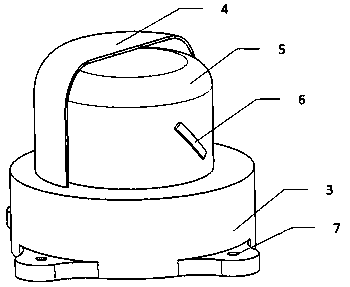
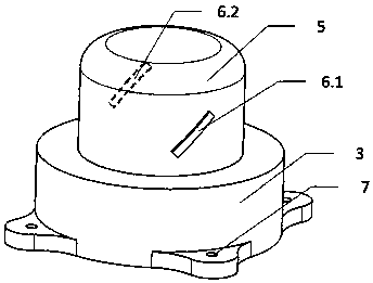
[0014] A laser emitting device for three-dimensional positioning, including a laser emitting rotating device, a control circuit board, a mounting base, and a transparent casing; the laser emitting rotating device includes a vertically installed, stable high-speed rotating motor and two laser emitting part. The two laser emitting parts are installed in the central part of the motor in the vertical direction, arranged on the symmetrical sides of the motor, forming a mirror image. The rotation of the motor can drive the two laser emitting parts to rotate synchronously.

[0015] The control circuit board is installed inside the mounting base, which saves equipment space.

[0016] There are four mounting holes on the mounting base for fixing the device body.

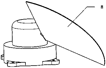
[0017] The laser emitting part will release the fan-shaped laser surface to the space, and the angle of the laser surface is in a degree angle relationship with the vertical direction of the motor, wherein the laser emittin...


PUM


Abstract

The invention discloses a laser emitting device for three-dimensional positioning. The laser emitting device comprises a laser emitting rotating device, a control circuit board, a mounting base and atransparent shell. The laser emitting rotating device comprises a motor and laser emitting parts. The control circuit board controls the rotating speed of the motor, and the motor drives the laser emitting device to rotate so as to achieve 360-degree laser coverage.

Description

technical field [0001] The invention describes a laser emitting device for three-dimensional space position and posture positioning. Background technique [0002] With the development of artificial intelligence robots and intelligent manufacturing, the demand for high-precision three-dimensional pose positioning is increasingly strong. At present, the solutions that can achieve high-precision three-dimensional positioning at the submillimeter level are mainly infrared images and lasers. The former is represented by Optitrack and vicon, but the cost is very high and there is serious delay. The latter is represented by the lighthouse technology developed by the game company Valve, which is mainly used in the field of virtual reality. The lighthouse technology scheme uses two high-speed rotating motors to emit lasers in both horizontal and vertical directions, and uses infrared flashlights for flash synchronization. There are two problems with this solution. One is that the t...

Claims


Application Information

Patent Timeline
IPC IPC(8): G01C15/00G01B11/00
CPCG01B11/00G01C15/002
Inventor 李宏达程宏宝
Owner NANJING ENIGMA IND AUTOMATION TECH CO LTD
Why Eureka
Try Eureka