
Flip chip thin film and display device

A chip-on-chip and display device technology, which is applied to optics, instruments, printed circuit components, etc., can solve problems such as poor wiring and abnormal lighting

Inactive Publication Date: 2019-11-19
TCL CHINA STAR OPTOELECTRONICS TECH CO LTD
View PDF6 Cites 0 Cited by
  • Summary
  • Abstract
  • Description
  • Claims
  • Application Information

AI Technical Summary

Problems solved by technology

After the liquid crystal display panel components go through the assembly process and the subsequent transportation process, there are easy torn points in the connection area between the chip-on-chip film, the liquid crystal panel, and the driving circuit board, which extend to the line area of ​​the chip-on-chip film after tearing, resulting in defective lines
As a result, abnormal lighting occurs when the LCD panel is turned on.

Method used


Image

  • Flip chip thin film and display device
  • Flip chip thin film and display device
  • Flip chip thin film and display device

Examples


Embodiment Construction

[0036] The technical solutions in the embodiments of the present application will be clearly and completely described below in conjunction with the drawings in the embodiments of the present application. Apparently, the described embodiments are only some of the embodiments of this application, not all of them. Based on the embodiments in this application, all other embodiments obtained by those skilled in the art without making creative efforts belong to the scope of protection of this application.

[0037] Embodiments of the present application provide a chip-on-chip film and a display device, which will be described in detail below.

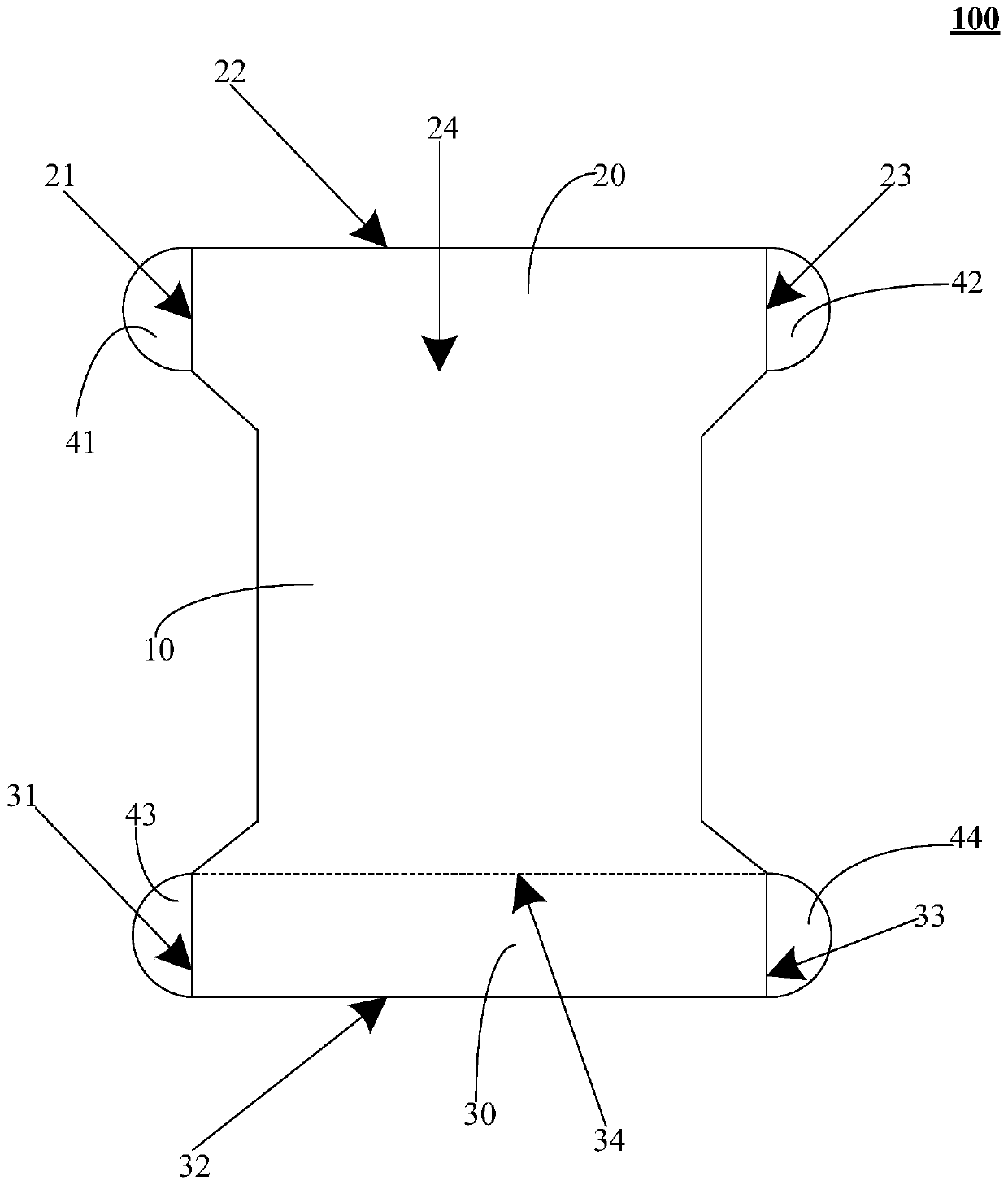
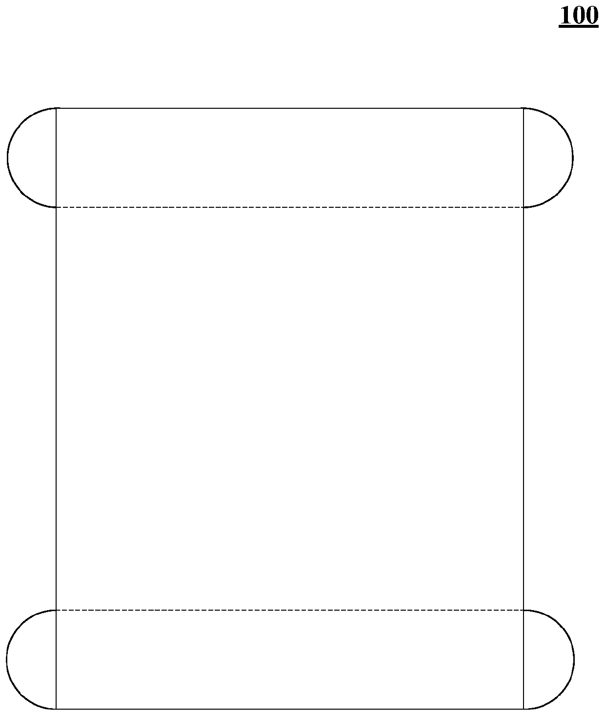
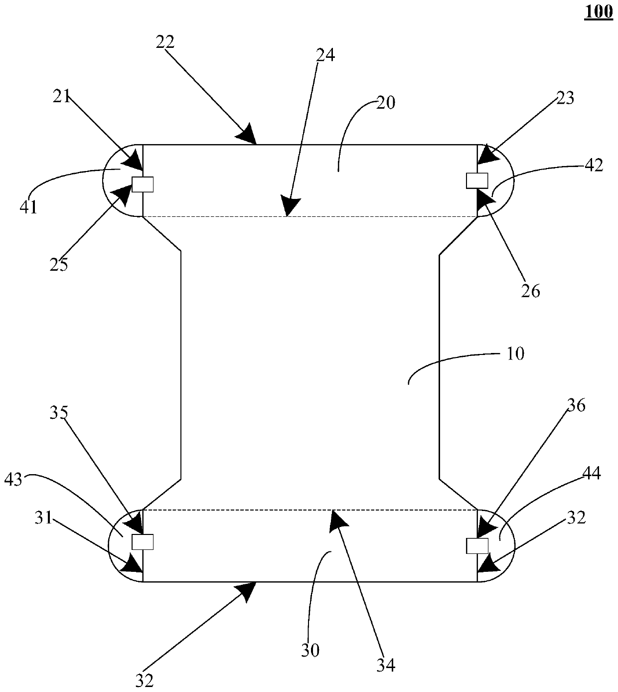
[0038] see figure 1 , figure 1 is a schematic structural view of the chip-on-film provided in the embodiment of the present application. The COF 100 may include: a main body 10 and a first connecting portion 20 and a second connecting portion 30 connected to two ends of the main body 10 . It should be noted that the shape of the COF 100 in...


PUM


Abstract

The embodiment of the invention discloses a flip chip thin film and a display device. The flip chip thin film comprises a main body, a first connection part and a second connection part, wherein the first connection part and the second connection part are connected to two ends of the main body, the first connection part comprises a first edge and a second edge which are oppositely arranged, the second connection part comprises a third edge and a fourth edge which are oppositely arranged, and a tear-resistant structure is arranged at least one of the first edge, the second edge, the third edgeand the fourth edge. With the flip chip thin film, the problem of unfavorable circuit caused by torn of the flip chip thin film can be reduced, and the quality of the display device is improved.

Description

technical field [0001] The present application relates to the field of display technology, in particular to a chip-on-chip film and a display device. Background technique [0002] Liquid crystal display panel components mainly include a liquid crystal panel, a chip-on-chip film and a driving circuit board. After the liquid crystal display panel components go through the assembly process and the subsequent transportation process, there are easy tear points in the connection area between the chip-on-chip film, the liquid crystal panel, and the driving circuit board, which extend to the line area of ​​the chip-on-chip film after tearing, resulting in defective lines . As a result, abnormal lighting occurs when the liquid crystal panel is turned on. Contents of the invention [0003] The embodiments of the present application provide a chip-on-chip film and a display device, which can avoid the circuit area of ​​the chip-on-chip film from being torn and cause defective circu...

Claims


Application Information

Patent Timeline
IPC IPC(8): G02F1/1345H05K1/02
CPCG02F1/13452H05K1/0281
Inventor 胡乾双
Owner TCL CHINA STAR OPTOELECTRONICS TECH CO LTD
Learn More