
Circuit board soldering fixture

A technology for welding jigs and circuit boards, which is applied in the direction of assembling printed circuits with electrical components, and can solve problems such as short circuits, affecting circuit board functions, and poor appearance.

Inactive Publication Date: 2016-08-31
AU OPTRONICS (XIAMEN) CORP +1
View PDF6 Cites 0 Cited by
  • Summary
  • Abstract
  • Description
  • Claims
  • Application Information

AI Technical Summary

Problems solved by technology

However, if manual pull welding is used, it is easy to cause various problems due to poor operator skills.
[0004] For example, if the operator cannot control the shape of the solder well, it is easy to cause the solder to stick to the circuit area, resulting in poor appearance. What's more, the sticky solder will cause a short circuit in the circuit, which will affect the function of the circuit board. damage
If the solder is not effectively soldered to the solder joint during soldering, it may cause the solder to fall off in the future, making the circuit board useless, or making the solder weak, affecting the function of the circuit board

Method used


Image

  • Circuit board soldering fixture
  • Circuit board soldering fixture
  • Circuit board soldering fixture

Examples


Embodiment Construction

[0033] The following will clearly illustrate the spirit of the present invention with illustrations and detailed descriptions. Those of ordinary skill in the art, after understanding the preferred embodiments of the present invention, can make changes and modifications based on the techniques taught in the present invention. without departing from the spirit and scope of the present invention.

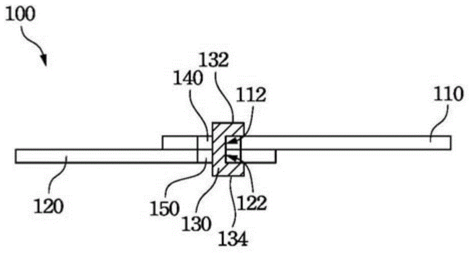
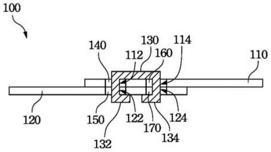
[0034] refer to figure 1 , which shows a schematic view of the first embodiment of the circuit board soldering structure using the circuit board soldering jig of the present invention. The circuit board welding structure 100 includes a first circuit board 110, a second circuit board 120, a welding wire 130 connecting the first circuit board 110 and the second circuit board 120, and a first solder joint 140 located on the first circuit board 110, And the second solder joint 150 on the second circuit board 120 . Wherein the first circuit board 110 has a first through hole 112 , and the...


PUM


Abstract

The invention provides a circuit board welding jig comprising a positioning device, a welding wire penetrating device and a first heating device. The positioning device is used for positioning a first circuit board and a second circuit board so as to be aligned to a first through hole in the first circuit board and a second through hole in the second circuit board. The welding wire penetrating device is used for enabling a welding wire to penetrate through the first through hole in the first circuit board and the second through hole in the second circuit board. The first heating device is used for welding the welding wire to the first circuit board and the second circuit board. By means of the circuit board welding jig, the circuit boards can be welded reliably and efficiently.

Description

[0001] This application is a divisional application of the invention patent application "circuit board welding structure and method and its jig" with the filing date of December 30, 2009 and the application number of 200910258899.6. technical field [0002] The invention relates to a circuit board welding jig, and in particular to a multilayer circuit board welding jig. Background technique [0003] In various electronic products, it is often necessary to solder two circuit boards with different functions to electrically connect the two circuit boards. However, if manual pull welding is adopted, various problems are likely to occur due to the poor technique of the operator. [0004] For example, if the operator cannot control the shape of the solder well, it is easy to cause the solder to stick to the circuit area, resulting in poor appearance. What's more, the sticky solder will cause a short circuit in the circuit, which will affect the function of the circuit board. dama...

Claims


Application Information

Patent Timeline
Patent Type & Authority Patents(China)
IPC IPC(8): H05K3/36
Inventor 田昕
Owner AU OPTRONICS (XIAMEN) CORP
Learn More