Wheel hub motor vehicle failure control method and vehicle control unit

A hub motor and failure control technology, applied in electric vehicles, control drives, vehicle components, etc., can solve problems such as the inability to guarantee vehicle driving safety, and achieve the effect of improving safety

Active Publication Date: 2019-11-22
WUHAN UNIV OF TECH
View PDF6 Cites 20 Cited by
  • Summary
  • Abstract
  • Description
  • Claims
  • Application Information

AI Technical Summary

Problems solved by technology

[0004] The purpose of the present invention is to overcome the above-mentioned technical deficiencies, provide a method for controlling failure of hub motor vehicles and a vehicle controller, and solve the problem of failure control of hub motors in the prior art. The technical problem that the remaining power cannot be guaranteed to ensure the driving safety of the vehicle

Method used


Image

  • Wheel hub motor vehicle failure control method and vehicle control unit
  • Wheel hub motor vehicle failure control method and vehicle control unit
  • Wheel hub motor vehicle failure control method and vehicle control unit

Examples


Embodiment 1

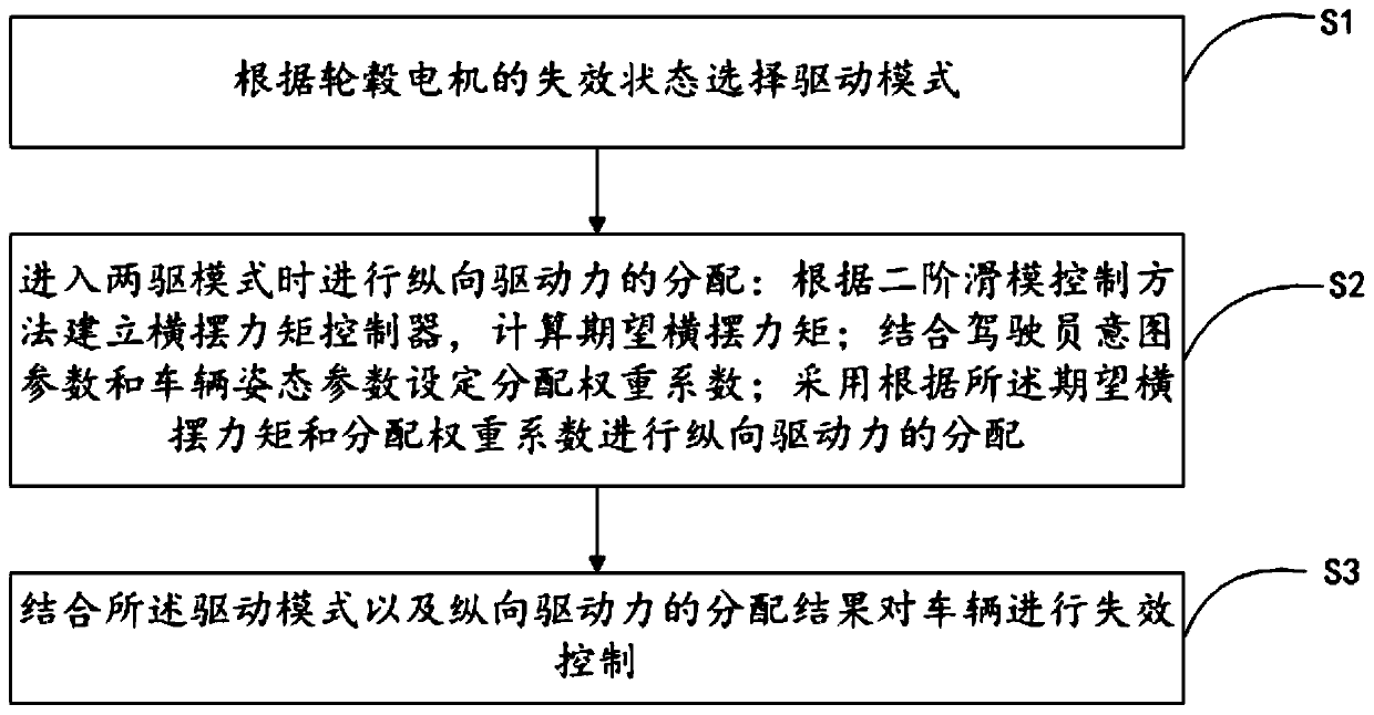
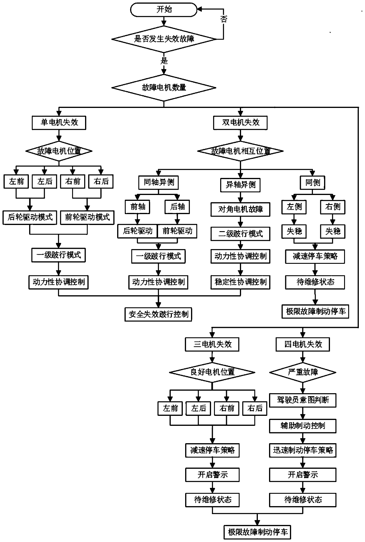
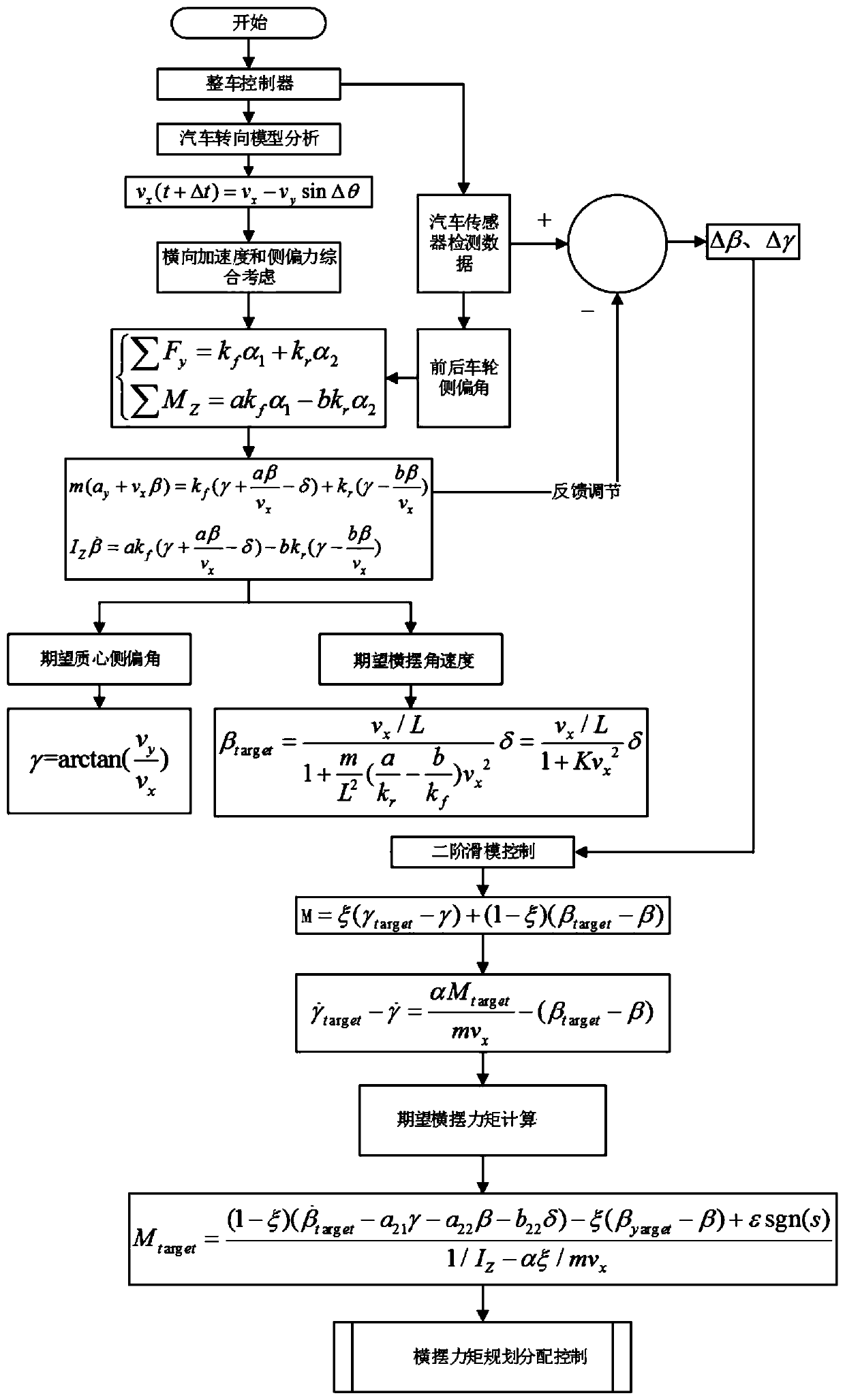
[0027] Such as figure 1 As shown, embodiment 1 of the present invention provides the in-wheel motor vehicle failure control method, hereinafter referred to as the control method, comprising the following steps:

[0028] S1. Select the driving mode according to the failure state of the hub motor;

[0029] S2. When entering the two-wheel drive mode, distribute the longitudinal driving force: establish a yaw moment controller according to the second-order sliding mode control method, and calculate the expected yaw moment; combine the driver's intention parameters and vehicle attitude parameters to set the distribution weight coefficient; according to The desired yaw moment and the distribution weight coefficient are used to distribute the longitudinal driving force;

[0030] S3. Perform failure control on the vehicle in combination with the driving mode and the distribution result of the longitudinal driving force.

[0031] During the driving process of the distributed drive ve...

Embodiment 2

[0142] Embodiment 2 of the present invention provides a vehicle controller, including a processor and a memory, and a computer program is stored in the memory. When the computer program is executed by the processor, the in-wheel motor provided by any of the above embodiments is realized. Vehicle failure control methods.

[0143] The in-wheel motor vehicle failure control method is specifically: select the driving mode according to the failure state of the in-wheel motor;

[0144] When entering the two-wheel drive mode, distribute the longitudinal driving force: establish a yaw moment controller according to the second-order sliding mode control method, and calculate the expected yaw moment; combine the driver's intention parameters and vehicle attitude parameters to set the distribution weight coefficient; according to the The desired yaw moment and distribution weight coefficient are used to distribute the longitudinal driving force;

[0145] Combined with the driving mode a...


PUM


Abstract

The invention relates to the technical field of wheel hub motor vehicle failure control, and discloses a wheel hub motor vehicle failure control method, which comprises the following steps of selecting a driving mode according to a failure state of a wheel hub motor; distributing the longitudinal driving force when entering a two-drive mode; establishing a yawing moment controller according to a second-order sliding mode control method, and calculating the expected yawing moment; setting a distribution weight coefficient in combination with a driver intention parameter and a vehicle attitude parameter; distributing the longitudinal driving force according to the expected yawing moment and the distribution weight coefficient; and performing failure control on the vehicle in combination withthe driving mode and the distribution result of the longitudinal driving force. According to the hub motor vehicle failure control method provided by the invention, the residual dynamic property canbe exerted on the premise of ensuring the safe driving of the vehicle, and the safe driving of the vehicle in a motor failure state is ensured.

Description

technical field [0001] The invention relates to the technical field of hub motor vehicle failure control, in particular to a hub motor vehicle failure control method and a vehicle controller. Background technique [0002] With the rapid development of the automobile industry, new energy vehicles have become the mainstream development direction of the automobile industry. For the development of in-wheel motor-driven vehicles in the electric vehicle industry, the distributed in-wheel motor drive system can independently control each wheel at any time, and directly send torque and other commands to the wheels through the motor controller. Compared with the traditional centralized control method, the distributed control method of the wheels is easier to exert the power of the vehicle and ensure the stability of the vehicle. At the same time, it also makes the driving conditions of the vehicle more complicated and requires higher fault tolerance. Therefore, the distributed Type ...

Claims


Application Information

Patent Timeline
IPC IPC(8): B60L15/20B60L3/00
CPCB60L15/20B60L3/0061B60L2220/44B60L2220/42B60L2260/26Y02T10/72
Inventor 付翔刘道远张强辉裴健吴森
Owner WUHAN UNIV OF TECH
Why Eureka
Try Eureka