A furnace door safety locking device

A locking device and safety technology, applied in furnaces, furnace components, lighting and heating equipment, etc., can solve the problems of unstable locking and laborious connection, etc., and achieve the effect of increasing the locking force

Active Publication Date: 2021-02-09
ANHUI FENGHUI METAL
View PDF4 Cites 0 Cited by
  • Summary
  • Abstract
  • Description
  • Claims
  • Application Information

AI Technical Summary

Problems solved by technology

[0003] Most of the existing locking methods are locked by bolt connection or card connection, which is not only laborious to connect but also not stable enough

Method used


Image

  • A furnace door safety locking device
  • A furnace door safety locking device
  • A furnace door safety locking device

Examples


Embodiment 1

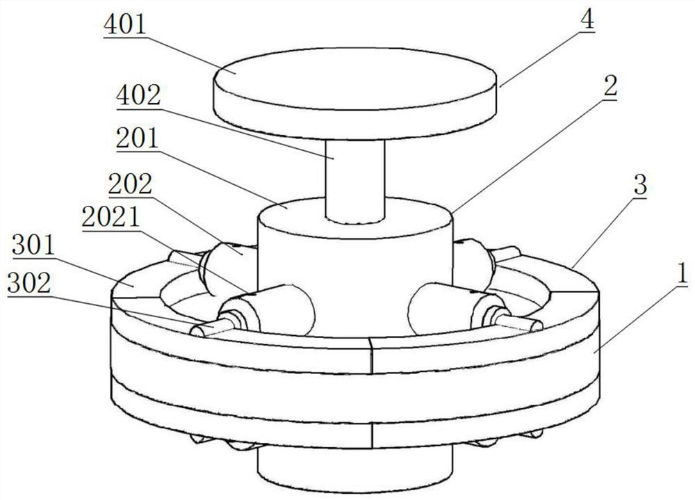
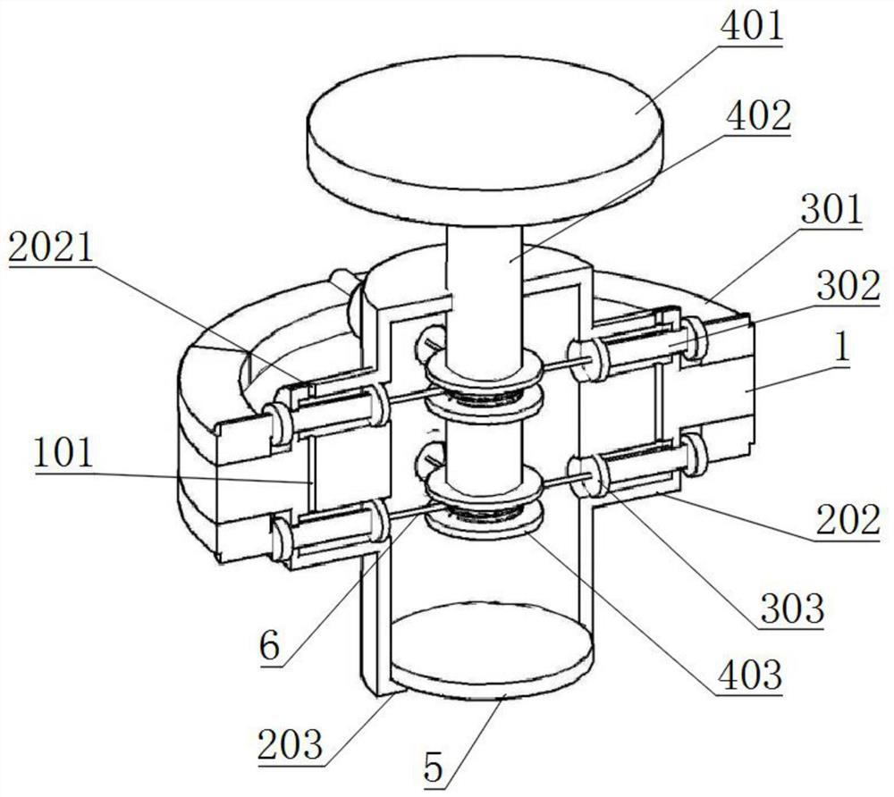
[0020] Such as Figure 1-3 A safety locking device for a furnace door is shown, comprising a sealed door, the sealed door includes a sealing plate 1, a pressure device 2 is provided in the middle of the sealing plate 1, and the pressure device 2 includes a pressure tube 201 penetrating through the sealing plate 1, and the pressure tube 201 is provided with a The piston 5 slidingly connected with it, the top of the pressure tube 201 is connected with the control mechanism 4, the control mechanism 4 is in transmission connection with the locking mechanism 3, the locking mechanism 3 is pneumatically connected with the pressure device 2, the locking mechanism 3 is slidingly connected with the sealing plate 1, and the pressure tube 201 The side is connected with the sliding cylinder 202, the sliding cylinder 202 is slidingly connected with the locking mechanism 3, the bottom end of the pressure tube 201 is open, and the bottom end of the inner wall of the pressure tube 201 is fixedl...

Embodiment 2

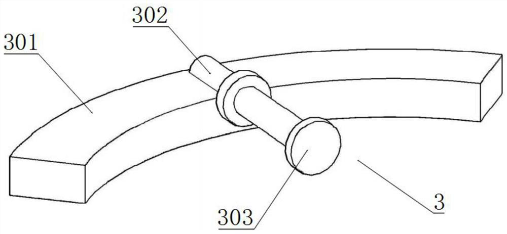
[0023] Such as Figure 1-3 As shown, a safety locking device for a furnace door includes a sealed door, and the sealed door includes a sealing plate 1. A pressure device 2 is provided in the middle of the sealing plate 1. The pressure device 2 includes a pressure tube 201 penetrating through the sealing plate 1. There is a piston 5 slidingly connected with it, and the top of the pressure tube 201 is connected with the control mechanism 4, the control mechanism 4 is in transmission connection with the locking mechanism 3, the locking mechanism 3 is pneumatically connected with the pressure device 2, the locking mechanism 3 is slidingly connected with the sealing plate 1, and the pressure tube The side of 201 communicates with the sliding cylinder 202, and the sliding cylinder 202 is slidingly connected with the locking mechanism 3. The shape of the chuck 301 is a hollow disc with an arc angle of 90 degrees. The vertical section of the chuck 301 is rectangular. The sliding cylind...


PUM


Abstract

The invention provides a furnace door safety locking device, which relates to the field of melting furnaces, and includes a sealed door, the sealed door includes a sealing plate, a pressure device is provided in the middle of the sealing plate, and the pressure device includes a pressure tube penetrating through the sealing plate, The pressure tube is provided with a piston slidingly connected with it, the top of the pressure tube is connected with a control mechanism, the control mechanism is in transmission connection with the locking mechanism, the locking mechanism is pneumatically connected with the pressure device, and the locking mechanism slides with the sealing plate connected, the side of the pressure pipe communicates with the sliding cylinder, and the sliding cylinder is slidably connected with the locking mechanism. In the present invention, the pressure in the furnace is used to move the piston in the pressure tube, thereby compressing the air in the pressure tube, and the pressure difference inside and outside the pressure tube is used to move the locking mechanism, so that the locking mechanism can connect the sealing plate and the furnace mouth more closely , increase the locking force, more secure.

Description

technical field [0001] The invention relates to the field of melting furnaces, in particular to a furnace door safety locking device. Background technique [0002] Melting furnaces are widely used in metal smelting. During metal smelting, the temperature in the furnace can reach more than 1,000 degrees, resulting in an increase in the pressure in the furnace. Since the furnace door and the furnace mouth are connected in a movable manner, its pressure-bearing capacity is higher than that of a furnace. The rest of the interior is relatively low. If the locking device is loose during the smelting process, the release of pressure in the furnace will easily lead to major accidents. Therefore, the connection and locking methods of the furnace door and the furnace mouth are particularly important. [0003] Most of the existing locking methods are bolted or clipped. The connection is laborious and the locking is not stable enough. Contents of the invention [0004] The object of ...

Claims


Application Information

Patent Timeline
Patent Type & Authority Patents(China)
IPC IPC(8): F27D1/18
CPCF27D1/1858
Inventor 张育玮张枫杨勇
Owner ANHUI FENGHUI METAL
Why Eureka
Try Eureka