
Multifunctional hydraulic piece maintaining platform

A technology of maintenance platform and hydraulic parts, applied in the field of maintenance platform, can solve the problems of inconvenient movement and inconvenient adjustment of the height of the maintenance platform, and achieve the effect of convenient movement, simple structure and convenient use

Active Publication Date: 2019-11-26
陕西神南天翊设备制造有限公司
View PDF10 Cites 0 Cited by
  • Summary
  • Abstract
  • Description
  • Claims
  • Application Information

AI Technical Summary

Problems solved by technology

[0004] The purpose of the present invention is to solve the disadvantages in the prior art that the height of the maintenance platform is inconvenient to adjust and not easy to move, and proposes a multi-functional maintenance platform for hydraulic parts

Method used


Image

  • Multifunctional hydraulic piece maintaining platform
  • Multifunctional hydraulic piece maintaining platform
  • Multifunctional hydraulic piece maintaining platform

Examples


Embodiment 1

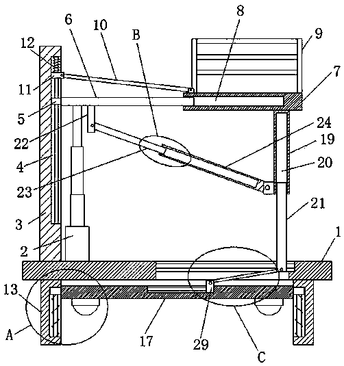
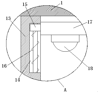
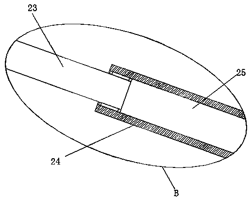
[0025] refer to Figure 1-5 , a multifunctional hydraulic parts maintenance platform, comprising a base 1, a hydraulic cylinder 2 is fixedly installed on the top of the base 1, a fixed plate 3 is fixedly installed on the top of the base 1, and two lifting grooves 4 are opened on one side of the fixed plate 3, Sliders 5 are slidingly installed in the two lifting grooves 4, and the same connecting plate 6 is fixedly installed on one side of the two sliding blocks 5, and the connecting plate 6 is located above the base 1, and the piston rod of the hydraulic cylinder 2 is fixedly installed on the connecting plate. The bottom of plate 6, sliding cover on connecting plate 6 is provided with platform plate 7, and platform plate 7 is provided with telescopic groove 8 near the side of fixed plate 3, and connecting plate 6 is slidably installed in telescopic groove 8, and the top of platform plate 7 is provided with There are guardrails 9, and the top of the platform plate 7 near the en...

Embodiment 2

[0034] refer to Figure 1-5, a multifunctional hydraulic parts maintenance platform, including a base 1, the top of the base 1 is fixedly installed with a hydraulic cylinder 2 by welding, the top of the base 1 is fixedly installed with a fixed plate 3 by welding, and one side of the fixed plate 3 is provided with two Lifting groove 4, sliders 5 are slidingly installed in the two lifting grooves 4, and the same connecting plate 6 is fixedly installed on one side of the two sliding blocks 5 by welding. The connecting plate 6 is located above the base 1, and the hydraulic cylinder 2 The piston rod is fixedly installed on the bottom of the connection plate 6 by welding, and the platform plate 7 is slidingly sleeved on the connection plate 6, and the side of the platform plate 7 close to the fixed plate 3 is provided with a telescopic groove 8, and the connection plate 6 is slidably installed in the telescopic groove 8 Inside, the top of the platform plate 7 is provided with a guar...


PUM


Abstract

The invention belongs to the technical field of maintaining platforms and particularly relates to a multifunctional hydraulic piece maintaining platform. Directing at the problems that the using height of an existing maintaining platform is inconvenient to adjust, and moving is inconvenient, the following scheme is put forwards, the multifunctional hydraulic piece maintaining platform comprises abase; a hydraulic cylinder is fixedly installed on the top of the base; a fixed plate is fixedly installed on the top of the base; one side of the fixed plate is provided with two lifting grooves; a slider is installed in each of the two lifting grooves in a sliding manner; one sides of the two sliders are fixedly provided with a same connection plate which is located above the base; a piston rodof a hydraulic cylinder is fixedly installed at the bottom of the connection plate which is sleeved with a platform plate in a sliding manner; the side, close to the fixed plate, of the platform plateis provided with a telescopic groove; the connection plate is installed in the telescopic groove in a sliding manner; the top of the platform plate is provided with a guard bar; and the using heightof the maintaining platform is inconvenient to adjust, and moving is inconvenient.

Description

technical field [0001] The invention relates to the technical field of maintenance platforms, in particular to a multifunctional maintenance platform for hydraulic components. Background technique [0002] The hydraulic parts maintenance platform is an operation platform for maintenance of various styles and models of hydraulic pumps, hydraulic cylinders, hydraulic motors, valve groups, etc. of industrial equipment, and is widely used in industry. [0003] The existing hydraulic parts maintenance platform has the problem that the height is not easy to adjust, and it is not convenient to move. Therefore, we propose a multifunctional hydraulic parts maintenance platform to solve the above problems. Contents of the invention [0004] The purpose of the present invention is to solve the disadvantages in the prior art that the height of the maintenance platform is inconvenient to adjust and not easy to move, and proposes a multifunctional hydraulic parts maintenance platform. ...

Claims


Application Information

Patent Timeline
IPC IPC(8): B25H1/16B25H1/18
CPCB25H1/16B25H1/18
Inventor 倪宇佩李祥至
Owner 陕西神南天翊设备制造有限公司
Learn More