Clamping component structure of industrial robot

An industrial robot, one-to-one corresponding technology, applied in the directions of chucks, manipulators, manufacturing tools, etc., can solve the problems of the object being clamped, such as vibration, and achieve the effect of firm clamping, easy unified control, and convenient operation.

Active Publication Date: 2019-11-26
佛山市文杰智能机械有限公司
View PDF14 Cites 6 Cited by
  • Summary
  • Abstract
  • Description
  • Claims
  • Application Information

AI Technical Summary

Problems solved by technology

[0004] The object of the present invention is to provide a clamping part structure of an industrial robot to solve the problem that the cla

Method used


Image

  • Clamping component structure of industrial robot
  • Clamping component structure of industrial robot
  • Clamping component structure of industrial robot

Examples


Embodiment 1

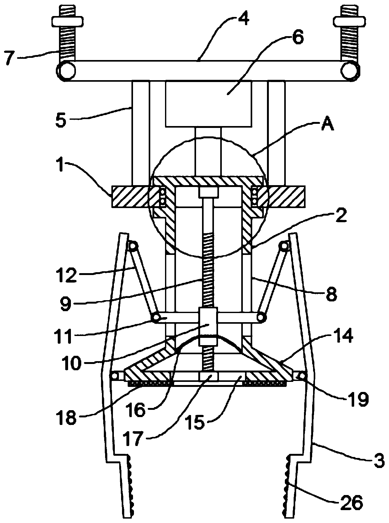
[0024] see Figure 1~3 , in an embodiment of the present invention, a clamping part structure of an industrial robot includes a fixed mounting plate 1, a fixed cylinder 2 mounted on the fixed mounting plate 1, and a plurality of clamping rods arranged on the outer wall of the fixed cylinder 2 Part 3, the bottom of the fixed cylinder 2 is provided with a suction cup body 14 in a cone structure and communicated with it, and the side wall of the suction cup body 14 is fixed with a hinge seat 19 corresponding to the clamping rod 3 one by one , the middle part of the clamping rod 3 is hinged on the corresponding hinge seat 19, the inside of the fixed cylinder 2 is provided with a pushing assembly that can toggle the clamping rod 3, and the pushing assembly includes a rotating set inside the fixed cylinder 2 Drive screw mandrel 9, the top of drive screw mandrel 9 is connected with the output shaft of electric control clamping motor 20 fixed on the top wall of fixed cylinder body 2, ...

Embodiment 2

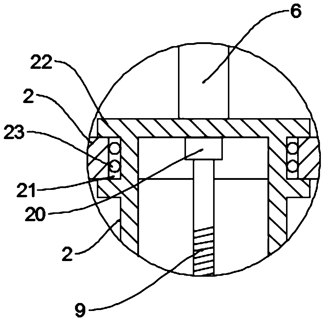
[0029] The difference between the embodiment of the present invention and embodiment 1 is that the fixed cylinder 2 is rotatably connected to the fixed installation plate 1, specifically, the middle part of the fixed cylinder 2 is provided with an installation through hole 21, and the fixed cylinder 2 2 pass through the installation through hole 21 and connect with the inner wall of the installation through hole 21 through the bearing 23, the outer wall of the top of the fixed cylinder 2 is provided with flanges 22 placed on both sides of the fixed cylinder 2 and the outer diameter of the flange 22 is larger than the installation The inner diameter of the through hole 21 prevents the fixed cylinder 2 from falling from the fixed mounting plate 1. An electric control rotary motor 6 is arranged on the top wall of the connecting plate 4, and the bottom end of the output shaft of the electric control rotary motor 6 is connected to the fixed The top of the cylinder body 2, driven by ...


PUM


Abstract

The invention discloses a clamping component structure of an industrial robot, relates to the technical field of industrial robots and mainly aims to solve the problem that a clamping head of the industrial robot only implements lateral clamping and may cause shake of a clamped object on the clamping part. The clamping component structure comprises a fixed mounting plate, a fixed cylinder body anda plurality of clamping rod parts, wherein the fixed cylinder body is installed on the fixed mounting plate; the clamping rod parts are arranged on the outer wall of the fixed cylinder body; the bottom of the fixed cylinder body is provided with a sucking disc body, wherein the sucking disc body is of a conical structure and communicates with the inside of the fixed cylinder body; the sidewall ofthe sucking disc body is fixedly provided with hinging seats corresponding to the clamping rod parts one by one; the middle part of each clamping rod part is hinged to the corresponding hinging seat;and a push component capable pulling the clamping rod parts is arranged inside the fixed cylinder body. The clamping component structure disclosed by the invention is simple in structure, improves the clamping firmness by virtue of multi-directional clamping, adopts united control drive, is convenient to operate and is relatively high in practicability.

Description

technical field [0001] The invention relates to the technical field of industrial robots, in particular to a clamping part structure of an industrial robot. Background technique [0002] An industrial robot is a multi-joint manipulator or a multi-degree-of-freedom machine device for the industrial field. It can perform work automatically and is a machine that realizes various functions by its own power and control capabilities. It can be commanded by humans or run according to pre-programmed programs. Modern industrial robots can also act according to the principles and programs formulated by artificial intelligence technology. The rotating base of the industrial robot is a supporting and fixing device arranged at the bottom of the industrial robot, and can rotate to adjust the position of the industrial robot. [0003] However, when the existing industrial robot grips the object, it only uses its clamping rod to clamp from its side. If there are ribs on the side of the obj...

Claims


Application Information

Patent Timeline
IPC IPC(8): B25J15/00B25J15/06
CPCB25J15/00B25J15/06B25J15/0616
Inventor 不公告发明人
Owner 佛山市文杰智能机械有限公司
Why Eureka
Try Eureka