Clamping device for wallboard

A clamping device and wallboard technology, applied in the direction of chucks, manipulators, manufacturing tools, etc., can solve problems such as overturning and easy slipping of wallboards, and achieve the effect of not being easy to fall over or skew

Active Publication Date: 2019-11-26
GUANGDONG BOZHILIN ROBOT CO LTD
View PDF8 Cites 1 Cited by
  • Summary
  • Abstract
  • Description
  • Claims
  • Application Information

AI Technical Summary

Problems solved by technology

For this reason, the present invention proposes a clamping device for wallboards, the clamping device can clamp the wallboards, the wallboards are not easy to overt

Method used


Image

  • Clamping device for wallboard
  • Clamping device for wallboard
  • Clamping device for wallboard

Examples


Embodiment Construction

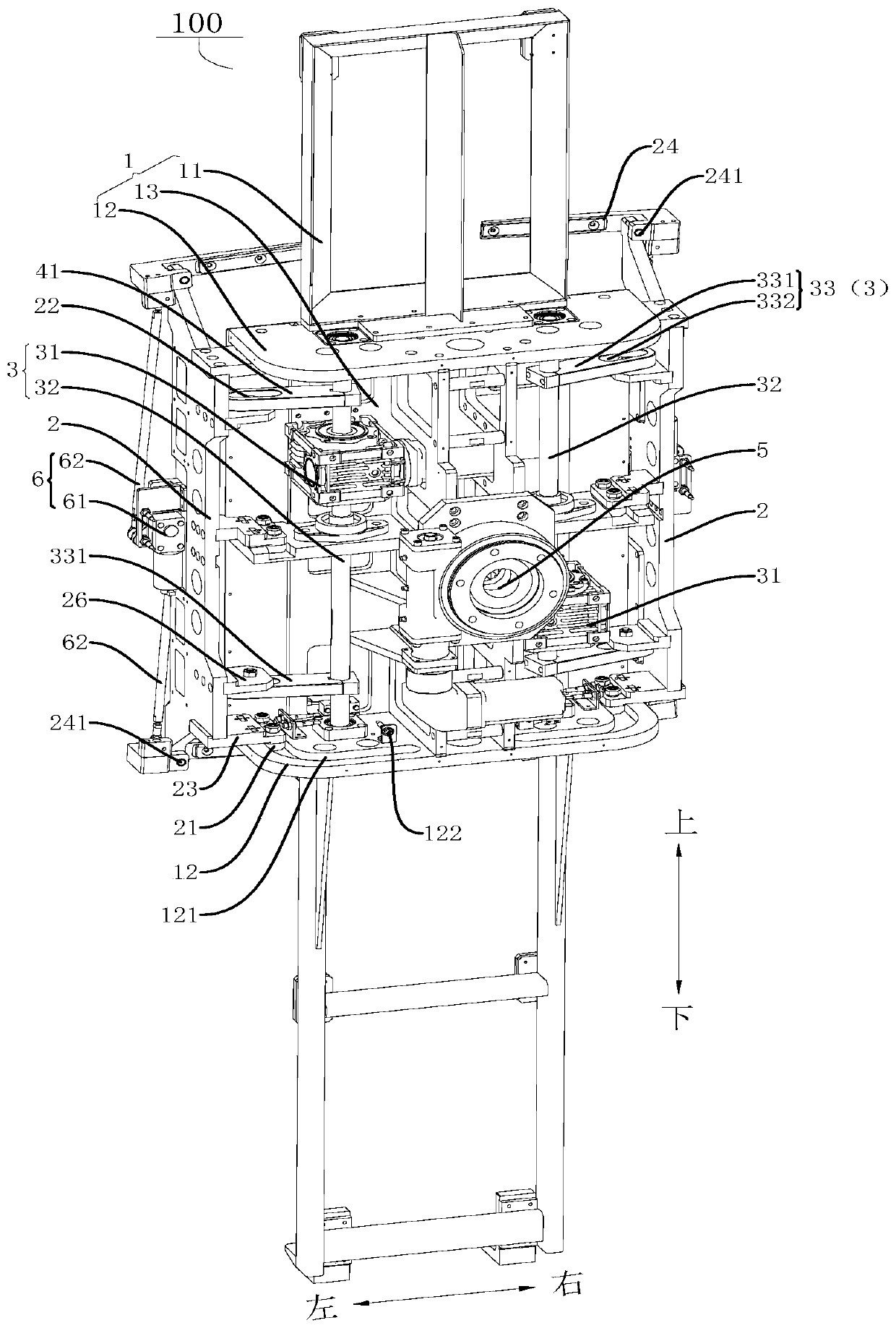
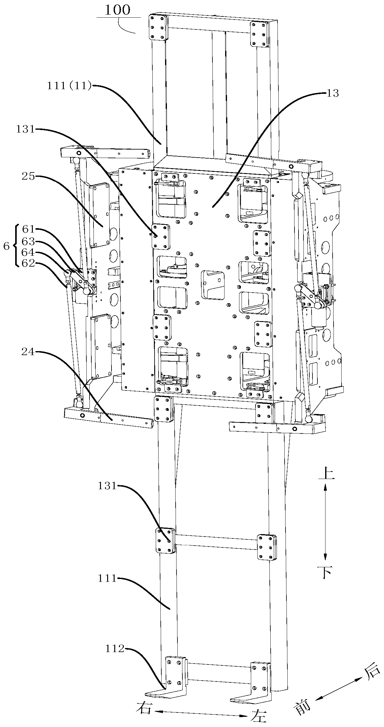
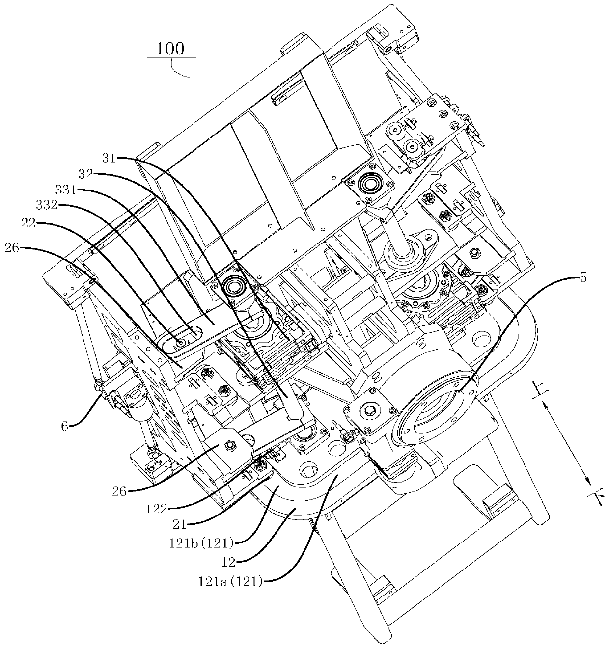
[0044] Embodiments of the present invention are described in detail below, examples of which are shown in the drawings, wherein the same or similar reference numerals designate the same or similar elements or elements having the same or similar functions throughout. The embodiments described below by referring to the figures are exemplary only for explaining the present invention and should not be construed as limiting the present invention.

[0045] In describing the present invention, it should be understood that the terms "center", "length", "width", "thickness", "upper", "lower", "front", "rear", "left", " The orientation or positional relationship indicated by "right", "vertical", "horizontal", "top", "bottom", "inner", "outer", etc. is based on the orientation or positional relationship shown in the drawings, and is for convenience only The present invention is described and simplified descriptions do not indicate or imply that the device or element referred to must have...


PUM


Abstract

The invention discloses a clamping device for a wallboard. The clamping device is used for clamping the wallboard. The clamping device includes a base, a clamping plate, a clamping claw, and a swing driving mechanism. The clamping plate is connected to the base, and the clamping plate can move relative to the base to limit the wallboard. The clamping claw is connected to the clamping plate in a swinging mode, and the moving surface of the clamping claw is perpendicular to the moving surface of the clamping plate. The swing driving mechanism is used for driving the clamping claw to swing between the open position and the storage position. The clamping claw is used for clamping the wallboard when in the open position, and the clamping claw is used for releasing the wallboard when in the storage position. In the clamping device, when the clamping device clamps the wallboard, the clamping plate can be moved to the side of the wallboard to limit the wallboard. Since the moving face of the clamping claw is perpendicular to that of the clamping plate, after the clamping plate is moved to one side face of the wallboard, the clamping claw is moved to the other side face of the wall plate after swinging, so that the wallboard is clamped. After the clamping device clamps the wallboard, the wallboard is not easy to fall or skew.

Description

technical field [0001] The invention belongs to the technical field of construction robots, in particular to a clamping device for wall panels. Background technique [0002] Most of the clamping mechanisms used in related technologies are pneumatically or hydraulically driven, and the mechanism is complex. Various valve bodies, gas-liquid sources, pipelines and other structures need to be installed, and the structure of the clamping jaws is small, which cannot clamp larger materials. Range limited. There are also clamping mechanisms that are prone to jams during the process of clamping materials, and the position during movement is far from the position of the power end, resulting in inability to move continuously during the clamping process. Also some clamping mechanisms cannot realize the handling, and the materials are easy to slip or skew during the clamping process. In addition, when the clamping mechanism clamps a large material, it is difficult to switch the posture...

Claims


Application Information

Patent Timeline
IPC IPC(8): B25J15/08B25J11/00
CPCB25J11/00B25J15/08
Inventor 张强军梁健斌
Owner GUANGDONG BOZHILIN ROBOT CO LTD
Why Eureka
Try Eureka