Special-shaped cutter mold and preparation method thereof

A cutting die and special-shaped technology, which is applied in the field of special-shaped cutting dies and its preparation, can solve the problems of unreasonable utilization of blades, increase of product defect rate, and reduction of material utilization rate, so as to improve material utilization rate, expand profit margin, reduce The effect of cutting pressure

Pending Publication Date: 2019-11-26
SHENZHEN SUNNYPOL OPTOELECTRONICS
View PDF0 Cites 0 Cited by
  • Summary
  • Abstract
  • Description
  • Claims
  • Application Information

AI Technical Summary

Problems solved by technology

The traditional special-shaped polarizer production method is to first cut into rectangular pieces and then use CNC equipment for processing. This kind of solution has a large margin for edging and low production efficiency. The solution of forming special-shaped small pieces
[0003] However, the existing special-shaped die cutting method has the following defects: as figure 1 As shown, the existing special-shaped die design adopts a mesh structure, that is, there is a gap of 4 to 5 mm between the blade and the blade, which will reduce the material utilization rate during cutting; in addition, the die blade generally adopts Zhongshan mirror imported from Japan Knives are expensive, the blades of the current scheme cannot be reasonably utilized, and the cost of the dies increases; moreover, there is a certain proportional relationship between the cutting pressure and the total meter of blades, the more blades are used, the greater the pressure required for cutting, and the The greater the cutting pressure, the higher the defective rate of the product

Method used


Image

  • Special-shaped cutter mold and preparation method thereof
  • Special-shaped cutter mold and preparation method thereof
  • Special-shaped cutter mold and preparation method thereof

Examples


preparation example Construction

[0038] A method for preparing a special-shaped die, comprising:

[0039]The step of setting mold cavities: take the base of the knife mold, set a number of mold cavities arranged in an array on the base of the knife mold, and the adjacent two mold cavities in the same row or column are respectively recorded as the first mold cavity and the second mold cavity, and the second A mold cavity includes a first linear cavity and a first non-linear cavity, a second mold cavity includes a second linear cavity and a second non-linear cavity, and the first linear cavity and the second linear cavity completely overlap , the first non-linear mold cavity and the second non-linear mold cavity are connected left and right; the two opposite mold cavities in different rows or columns are respectively recorded as the first mold cavity and the third mold cavity, and the third mold cavity includes a third linear hole and a third non-linear hole, a gap is provided between the first linear hole and ...

Embodiment 1

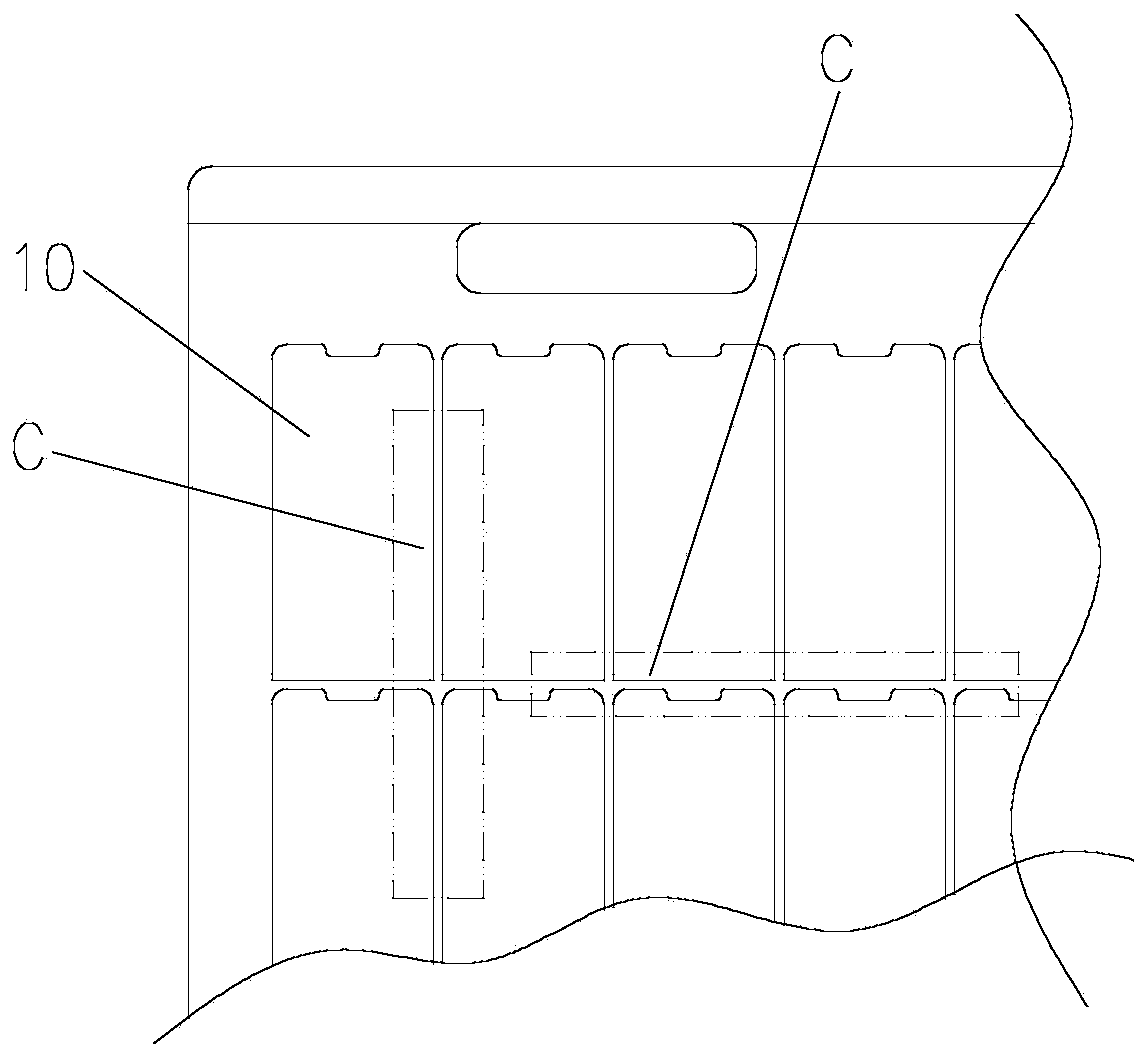
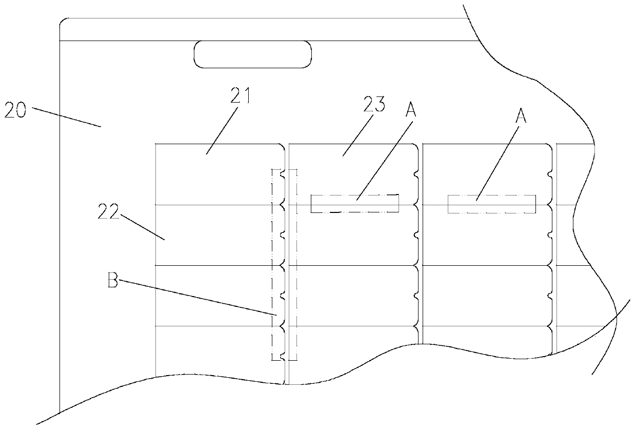
[0043] like figure 2 As shown, a special-shaped knife mold includes a knife mold base 20, several mold cavities and several blades; several mold cavities are arrayed on the knife mold base 20 in the form of 18 rows and 4 columns; two adjacent mold cavities in the same column Respectively denoted as the first mold cavity 21 and the second mold cavity 22, the first mold cavity 21 includes the first linear cavity and the first non-linear cavity, and the second mold cavity 22 includes the second linear cavity and the second non-linear cavity shaped cavity, the first linear mold cavity and the second linear mold cavity completely overlap (see area A), and the first non-linear mold cavity and the second non-linear mold cavity are connected left and right (such as Figure 4 As shown, the common knife place is directly welded together, see area D); The two adjacent mold cavities facing each other are respectively marked as the first mold cavity 21 and the third mold cavity 23, and th...

Embodiment 2

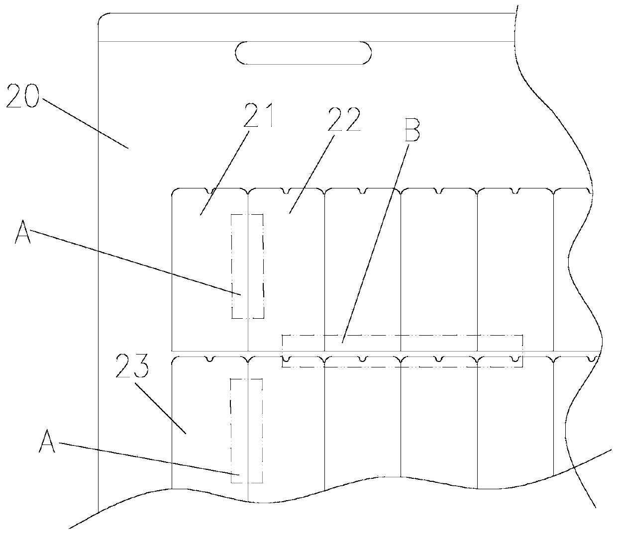
[0045] like image 3 As shown, the difference between embodiment 2 and embodiment 1 is that the mold cavities are arrayed on the die matrix 20 in the form of 8 rows and 9 columns, and the adjacent two mold cavities in the same row are respectively marked as the first The mold cavity 21 and the second mold cavity 22, two adjacent rows of directly opposite mold cavities are respectively marked as the first mold cavity 21 and the third mold cavity 23.

[0046] Others are identical with specific embodiment 1.


PUM


Abstract

The invention discloses a special-shaped cutter mold and a preparation method thereof. The special-shaped cutter mold comprises a cutter mold base body, mold cavities and blades; the mold cavities arearranged on the cutter mold base body; two adjacent mold cavities of the same row or column are marked as a first mold cavity and a second mold cavities correspondingly, wherein the first mold cavitycomprises a first linear mold cavity and a first non-linear mold cavity, the second mold cavity comprises a second linear mold cavity and a second non-linear mold cavity, the first linear mold cavityand the second linear mold cavity are overlapped, and the first non-linear mold cavity is connected to the second non-linear mold cavity left and right; the two opposite mold cavities of different rows or columns are marked as a first mold cavity and a third mold cavity correspondingly, wherein the third mold cavity comprises a third linear mold cavity and a third non-linear mold cavity, and a gap is formed between the first linear mold cavity and the third non-linear mold cavity; and the blades are arranged in the mold cavities. According to the special-shaped cutter mold, the common cutterdesign is adopted among the mold cavities, so that the use quantity of the blades is greatly reduced, then the manufacturing cost of the cutter mold is reduced, the number of the blades is reduced, the cutting pressure is correspondingly reduced, and the product reject ratio is reduced.

Description

technical field [0001] The invention relates to the technical field of cutting dies, in particular to a special-shaped cutting die and a preparation method thereof. Background technique [0002] With the continuous development of mobile phone full-screen technology, special-shaped solutions have sprung up, and major manufacturers are competing to apply them. Polarizers, one of the three major components of liquid crystal displays, are also looking for mature special-shaped production solutions. The traditional special-shaped polarizer production method is to first cut into rectangular pieces and then use CNC equipment for processing. This kind of solution has a large margin for edging and low production efficiency. A solution for forming small shaped pieces. [0003] However, the existing special-shaped die cutting method has the following defects: as figure 1 As shown, the existing special-shaped die design adopts a mesh structure, that is, there is a gap of 4 to 5 mm be...

Claims


Application Information

Patent Timeline
Patent Type & Authority Applications(China)
IPC IPC(8): B26F1/44B26D7/26
CPCB26D7/2614B26D2007/2607B26F1/44
Inventor 陈恒彭连启阮志毅张汉平
Owner SHENZHEN SUNNYPOL OPTOELECTRONICS
Why Eureka
Try Eureka