
Airflow ejector adopting annular swirl injection

A technology of ejector and annular nozzle, which is applied in the field of recovery devices for diffused gas, can solve problems such as no public reports, and achieve significant economic and social benefits

Inactive Publication Date: 2019-11-26
郑州釜鼎热能技术有限公司
View PDF8 Cites 4 Cited by
  • Summary
  • Abstract
  • Description
  • Claims
  • Application Information

AI Technical Summary

Problems solved by technology

For this reason, a method is proposed to allow the ejected recycled air flow to realize sonic or supersonic flow when it is self-flowing, and to adopt a circular ejection method in order to improve the ejection effect when ejected by the ejected air flow, and to make the ejected air flow flow in a Ejectors with sonic or even supersonic jets, so as to realize the rapid self-flow and high-efficiency ejection of the recovered airflow to the normal pressure state, but there has been no public report so far

Method used


Image

  • Airflow ejector adopting annular swirl injection
  • Airflow ejector adopting annular swirl injection

Examples


Embodiment Construction

[0008] The specific implementation manners of the present invention will be described in detail below in conjunction with the accompanying drawings.

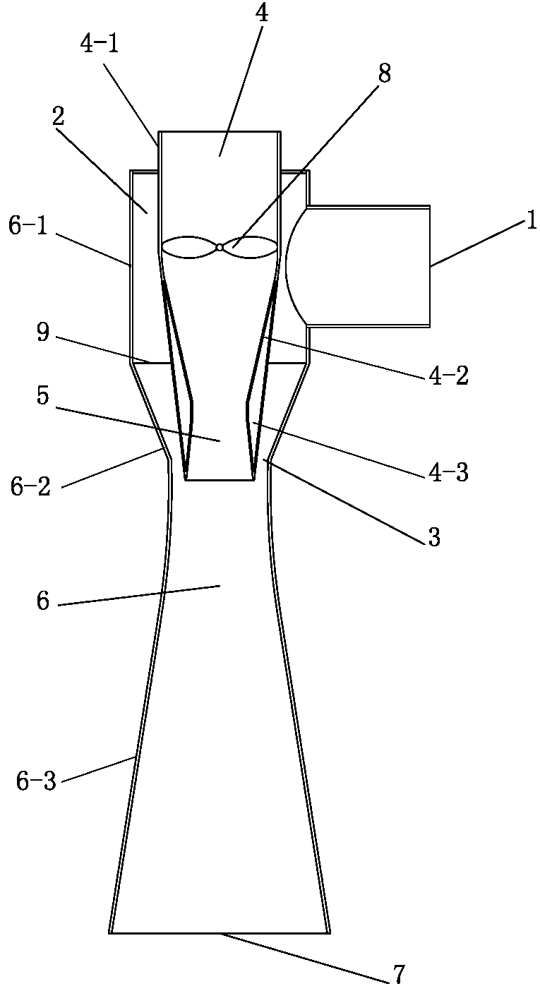
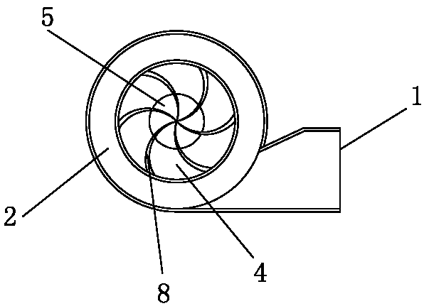
[0009] Such as figure 1 , figure 2 As shown, the present invention adopts the airflow ejector of annular swirl jet, comprises the ejection airflow inlet pipe 1, the ejected airflow inlet pipe 4 and the mixed airflow diffuser pipe 6, and the airflow ejector is formed by the ejected airflow inlet pipe 4 and the mixed airflow diffuser pipe 6. The airflow inlet pipe 4 is set in a sleeve tubular zoom structure formed in the upper center of the mixed airflow diffuser pipe 6. The ejected airflow inlet pipe 4 is composed of a first straight pipe section 4-1 and a first tapered section 4-2. 1. An integrated structure formed by connecting the first scaling section 4-3, and the mixed air flow diffuser pipe 6 is formed by connecting the second straight pipe section 6-1, the second tapering section 6-2, and the second zooming section 6-3 ...


PUM


Abstract

The invention relates to an airflow ejector adopting annular swirl injection. The problems that high pressure recovery airflow fast flows and is efficiently ejected to the normal pressure state are solved effectively. An ejected airflow inlet pipe is installed in the upper portion of the center of a mixed airflow diffusion pipe in a sleeved mode. The upper end of a first straight pipe section stretches out of the upper portion of the center of a second straight pipe section. The lower end of the ejected airflow inlet pipe is arranged in the center of the joint of a second gradual contraction section and a second contraction-expansion section and stretches into the upper portion of the second contraction-expansion section. An ejection airflow annular channel is formed between the second straight pipe section and the outer wall of the ejected airflow inlet pipe. A first contraction-expansion section forms an ejected airflow contraction-expansion nozzle which contracts first and then expands. An ejection airflow inlet pipe is installed on the outer wall of the second straight pipe section in a rotary-cut mode. A contraction-expansion annular nozzle is formed between the outer wall ofthe second gradual contraction section and the inner wall of the first contraction-expansion section. The mixed airflow diffusion pipe and a center cavity of the ejected airflow inlet pipe form a mixed airflow diffusion channel in the axial direction. An ejected airflow swirl deflector is installed in the position, close to an upper opening of a first gradual contraction section, in the first straight pipe section.

Description

technical field [0001] The invention relates to a recovery device for diffused gas, in particular to an air flow injector adopting annular swirl jet. Background technique [0002] During the operation of industrial equipment and systems, there is often the release of residual gas in the process. How to treat it harmlessly and how to recycle it for effective use are important issues of environmental protection and energy conservation that need to be considered in the process. In particular, it is necessary to adopt certain technical measures to actively dispose of some high-temperature or high-pressure and environmentally harmful polluting gases or combustible gas discharge (or release) waste gas recovery. For example, the high-pressure diffused gas used for gas balance in the charging system of the blast furnace must be recycled from the perspective of energy saving and environmental protection. In such a recovery system, the high-pressure gas is generally recovered to the ...

Claims


Application Information

Patent Timeline
Patent Type & Authority Applications(China)
IPC IPC(8): F04F5/16F04F5/46F04F5/44B01F5/04
CPCF04F5/16F04F5/465F04F5/44B01F25/312
Inventor 陈维汉陈云鹤杨海涛张佳鹏
Owner 郑州釜鼎热能技术有限公司
Learn More