Building construction rainfall drainage structure

A technology of drainage structure and building construction, applied in drainage structures, buildings, general water supply saving, etc., can solve the problems of slow drainage, increase project cost, incomplete drainage of accumulated water, etc., and achieve the effect of improving drainage rate

Inactive Publication Date: 2020-12-15
江苏金鼎建设集团有限公司
View PDF0 Cites 3 Cited by
  • Summary
  • Abstract
  • Description
  • Claims
  • Application Information

AI Technical Summary

Problems solved by technology

However, these measures often lead to incomplete drainage of accumulated water, resulting in mottled water stains on the roadside, poor road cleanliness, and unfavorable movement of people; in addition, the untreated sewage discharged on site contains many impurities, dirt and metal particles. Pollution to geology, groundwater or river water; the drainage speed is slow, and a large amount of manual treatment of accumulated water is required on the project, which increases the project cost

Method used


Image

  • Building construction rainfall drainage structure
  • Building construction rainfall drainage structure
  • Building construction rainfall drainage structure

Examples


Embodiment Construction

[0018] In order to make the technical means, creative features, goals and effects achieved by the present invention easy to understand, the present invention will be further described below in conjunction with specific embodiments.

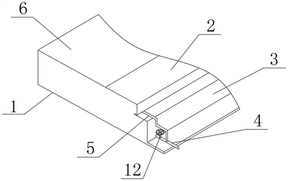
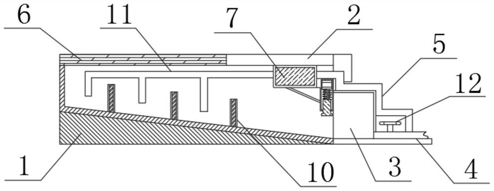
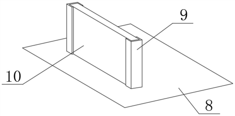
[0019] Such as Figure 1-4 As shown, a construction rainfall drainage structure includes a base 1 and an upper cover plate 2, a water storage tank 3 is arranged on the right side of the base 1, and an outlet pipe 4 is arranged at the bottom right corner of the bottom of the water storage tank 3, and the upper part of the outlet pipe 4 The surface position is connected with a conduit 5, the upper cover plate 2 is located at the upper right position of the base 1, the water seepage plate 6 is arranged on the left side of the upper cover plate 2, and the water pump 7 is arranged directly below the upper cover plate 2, and the base 1 A slope 8 is provided on the upper surface.

[0020] The inclined plane 8 is fixedly connected to the left side of the...


PUM


Abstract

The invention discloses a building construction rainfall drainage structure. The structure comprises a base and an upper cover plate, wherein a water storage tank is arranged on the right side of thebase, a water outlet pipe is arranged at the lower right corner of the bottom of the water storage tank, a guide pipe is connected to the upper surface of the water outlet pipe, the upper cover plateis located on the upper right portion of the base, a water seepage plate is arranged on the left side of the upper cover plate, a water suction pump is arranged under the upper cover plate, and an inclined surface is arranged on the upper surface of the base. According to the building construction rainfall drainage structure, rainwater can be filtered, and the situation that the rainwater carriesimpurities such as dust to enter the structure, and consequently the water outlet pipe is blocked is prevented; meanwhile, through a floating rod and a microswitch, according to the height of the liquid level of accumulated water, the working state of the water suction pump is automatically controlled, automation of drainage is achieved, and the whole drainage structure is simple in principle, practical and suitable for popularization.

Description

technical field [0001] The invention relates to the technical field of building construction equipment, in particular to a rainwater drainage structure for building construction. Background technique [0002] At present, buildings are subject to rainfall in the environment, and the rainwater is generally discharged to the sewage channel through rainwater pipes. During the construction process, the precipitation and accumulated water on the construction site are comprehensively discharged and utilized to ensure the cleanliness of the construction site and increase the use of water resources. The intensity of recycling can achieve the goals of water saving, energy saving and environmental protection, while reducing operating costs. Therefore, the treatment of on-site water accumulation is an important issue. The measures often taken by on-site construction personnel and project managers for rainwater and on-site water accumulation are Submersible sewage pumps are used to extra...

Claims


Application Information

Patent Timeline
Patent Type & Authority Applications(China)
IPC IPC(8): E03F5/10E03F5/14E03F5/22E03B3/02E01C11/22B01D29/56H01H35/18
CPCB01D29/56E01C11/22E03B3/02E03F5/10E03F5/14E03F5/22H01H35/18Y02A20/108Y02A30/60
Inventor 孙鑫祥王进马彬玮胡仁军
Owner 江苏金鼎建设集团有限公司
Why Eureka
Try Eureka