[0057] Example
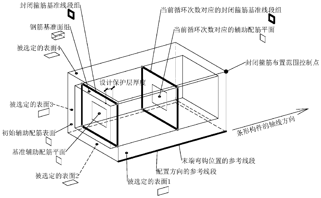
[0058] like Figure 1 to Figure 7 As shown, the computer-aided design method of the external closed stirrups of concrete bridge strip components; based on the CATIA software environment, and the concrete bridge components are modeled using the BIM model; in the BIM model of the concrete bridge components, multiple continuous intersections and The component surfaces that can form closed space graphics are used as the selected surface group, and the specific steps to generate closed stirrups are as follows:
[0059] Step 1. Offset the selected surface group according to the design cover thickness of the reinforcement, and the offset direction is to the inner side of the concrete bridge member;
[0060] Create multiple surfaces corresponding to multiple continuous surfaces in the selected surface group to form a steel bar datum face group, where multiple continuous surfaces in the steel bar datum face group are continuously intersected and form a closed space graphic structure;
[0061] The selected surface group and reinforcement datum face group are plane groups or surface groups, and each surface of the selected surface group is parallel to the corresponding surface in the reinforcement datum face group;
[0062] Rebar datum groups are used to locate the centerlines of closed stirrups;
[0063] Step 2. According to the design requirements, select the most representative edge in the selected surface group as the reference line segment of the first closed stirrup in the configuration direction;
[0064] Step 3. According to the design requirements, select an edge in the selected surface group as a reference line segment for the position of the end hook of the closed stirrup;
[0065] Step 4. According to the design requirements, select the most representative surface on the strip member as the initial auxiliary reinforcement surface, which is used to provide reference for the plane shape of the closed stirrup; the initial auxiliary reinforcement surface is not in the selected In a surface group or a reinforcement datum surface group;
[0066] Step 5. According to the design cover thickness, offset the initial auxiliary reinforcement surface, the offset direction is the axis direction of the reference line segment along the configuration direction, and offset towards the inner side of the concrete member;
[0067] Create a reference auxiliary reinforcement plane, which is parallel to the initial auxiliary reinforcement surface;
[0068] Step 6. Utilize the intersect function in the CATIA software to solve the line segment group intersected by the reference auxiliary reinforcement plane and the reinforcement reference surface group, that is, the closed stirrup reference line segment group;
[0069] Step 7, based on the closed stirrup datum line segment group, create the center line of the first closed stirrup;
[0070] Step 8. According to the design requirements, designate the farthest end point where the closed stirrups need to be arranged as the control point of the closed stirrup arrangement range;
[0071] Calculate the spatial distance from the control point of the closed stirrup layout range to the reference auxiliary reinforcement plane and subtract the corresponding protective layer thickness, and the resulting distance is taken as the value of the closed stirrup layout range;
[0072] Step 9, dividing the closed stirrup layout range by the closed stirrup layout spacing in the design requirements, rounding the result to an integer to obtain the number of closed stirrup spacing;
[0073] Step 10, utilizing the knowledge engineering array function in CATIA or based on the C# language programming function or based on the VBA language programming function, create a cycle program, the number of cycles is the number of closed stirrup spacing, and the steps performed in each cycle are as follows:
[0074] Step 10.1, according to the layout spacing of the closed stirrups according to the design requirements, the product of the current number of cycles multiplied by the layout spacing of the closed stirrups is used as the control distance, and the reference auxiliary reinforcement plane is offset to obtain the auxiliary reinforcement plane corresponding to the current number of cycles;
[0075] Step 10.2, using the intersection function in the CATIA software, solve the line segment that the auxiliary reinforcement plane corresponding to the current number of cycles intersects with the steel bar reference surface group, and use this line segment as the closed stirrup reference line segment group corresponding to the current cycle number;
[0076] Step 10.3, use the spatial distance calculation function in the CATIA software to solve the closest point from several control points in the closed stirrup reference line segment group corresponding to the current cycle number to the reference line segment at the end hook position, and use this point as the current cycle The end point of the closed stirrup corresponding to the number of times;
[0077] Step 10.4, according to the length of the hook at the end of the closed stirrup and the bending angle of the hook at the end of the closed stirrup according to the design requirements, at the end point of the closed stirrup corresponding to the current number of cycles, according to the design requirements, make 2 auxiliary points corresponding to the current number of cycles The length line segment of the closed stirrup hook corresponding to the current number of cycles on the reinforcement plane;
[0078] The length of the closed stirrup hook length line segment corresponding to the current number of cycles is equal to the length of the closed stirrup end hook;
[0079] Take the 2 line segments of the closed stirrup reference line segment group corresponding to the current cycle number that pass through the closed stirrup end point corresponding to the current cycle number as the closed stirrup end line segment corresponding to the current cycle number", and each closed stirrup corresponding to the current cycle number The obtuse angle of the plane angle formed by the line segment of the length of the hook of the tendon and the line segment of the end of the closed stirrup corresponding to the current number of cycles is equal to the bending angle of the hook at the end of the closed stirrup;
[0080] Step 10.5, using the function of stretching entities along the line in the CATIA software, using the closed stirrup reference line segment group corresponding to the current cycle number, the closed stirrup hook length line segment corresponding to the current cycle number as the stretching line, and the steel bar diameter as the outline, Create a steel solid model;
[0081] Step 10.6, calculate the total length of the center line of the closed stirrup corresponding to the current number of cycles, and its value is equal to 1 group of closed stirrup reference line segments corresponding to the current cycle number and 2 closed stirrup hooks corresponding to the current cycle number the sum of the lengths of the length line segments;
[0082] Step 10.7, adjust the total length of the closed stirrup as a global parameter, and count the total length of the center line of the closed stirrup corresponding to the current number of cycles in cumulative form;
[0083] Step 11. Using the user-defined feature function in CATIA software, the selected surface group, the initial auxiliary reinforcement surface, the reference line segment of the configuration direction and the control points of the closed stirrup layout range are used as input conditions to design the thickness of the protective layer, The length of the hook at the end of the closed stirrup, the bending angle of the hook at the end of the closed stirrup, the arrangement distance of the closed stirrup, and the total length of the closed stirrup are used as control parameters to establish a template for batch arrangement of closed stirrups in a certain direction on the surface of the concrete bridge member.
[0084] In some embodiments, the reference line segment of the end hook position and the reference line segment of the deployment direction are the same line segment.
[0085] In some embodiments, in step 7, based on the closed stirrup reference line segment group, the specific steps of creating the center line of the first closed stirrup are as follows:
[0086] Step 7.1, using the spatial distance calculation function in the CATIA software, solve the nearest point from several control points in the reference line segment group of the closed stirrup to the reference line segment of the end hook position, and use this point as the end point of the closed stirrup;
[0087] Step 7.2. According to the length of the hook at the end of the closed stirrup and the bending angle of the hook at the end of the closed stirrup according to the design requirements, make two closed stirrup bends at the end point of the closed stirrup according to the design requirements on the reference auxiliary reinforcement plane hook length segment;
[0088] The length of the hook length line segment of the closed stirrup is equal to the length of the hook at the end of the closed stirrup;
[0089] The two line segments passing through the end point of the closed stirrup in the reference line segment group of the closed stirrup are used as the end line segment of the closed stirrup, and the obtuse angle of the plane angle formed by each line segment of the hook length of the closed stirrup and the end line segment of the closed stirrup is equal to the closed stirrup Bending angle of the hook at the end of the stirrup;
[0090] Step 7.3, using the function of stretching entities along the line in the CATIA software, using the closed stirrup reference line segment group and the closed stirrup hook length line as the stretching line, and taking the steel bar diameter as the outline, a solid model of the steel bar is established;
[0091] Step 7.4, calculate the total length of the center line of the first closed stirrup, its magnitude is equal to the sum of the lengths of 1 group of closed stirrup reference line segment groups and 2 closed stirrup hook length segments;
[0092] Step 7.5: Add the total length of the closed stirrup as a global parameter, the type is length, and set the initial value of the total length of the closed stirrup as the total length of the center line of the first closed stirrup.