
Spraying machine for machining and producing automobile parts

A technology of auto parts and spraying machines, applied in the direction of spraying devices, etc., can solve the problems of imperfect structure, inconvenient adjustment of spraying angle, inconvenient parts, etc.

Active Publication Date: 2019-11-29
广德中晨电子科技有限公司
View PDF3 Cites 9 Cited by
  • Summary
  • Abstract
  • Description
  • Claims
  • Application Information

AI Technical Summary

Problems solved by technology

[0004] In order to solve the above technical problems, the present invention provides a spraying machine for the processing and production of auto parts, to solve the problem that the structure of controlling the uniform spraying is not perfect when the existing auto parts spraying machine is spraying, and it is not convenient to make the parts through control. The spraying color is uniform, and the existing auto parts spraying machine is not perfect in the structure of adjusting the spraying angle of the spraying head, and it is not convenient to adjust the spraying angle according to the demand

Method used

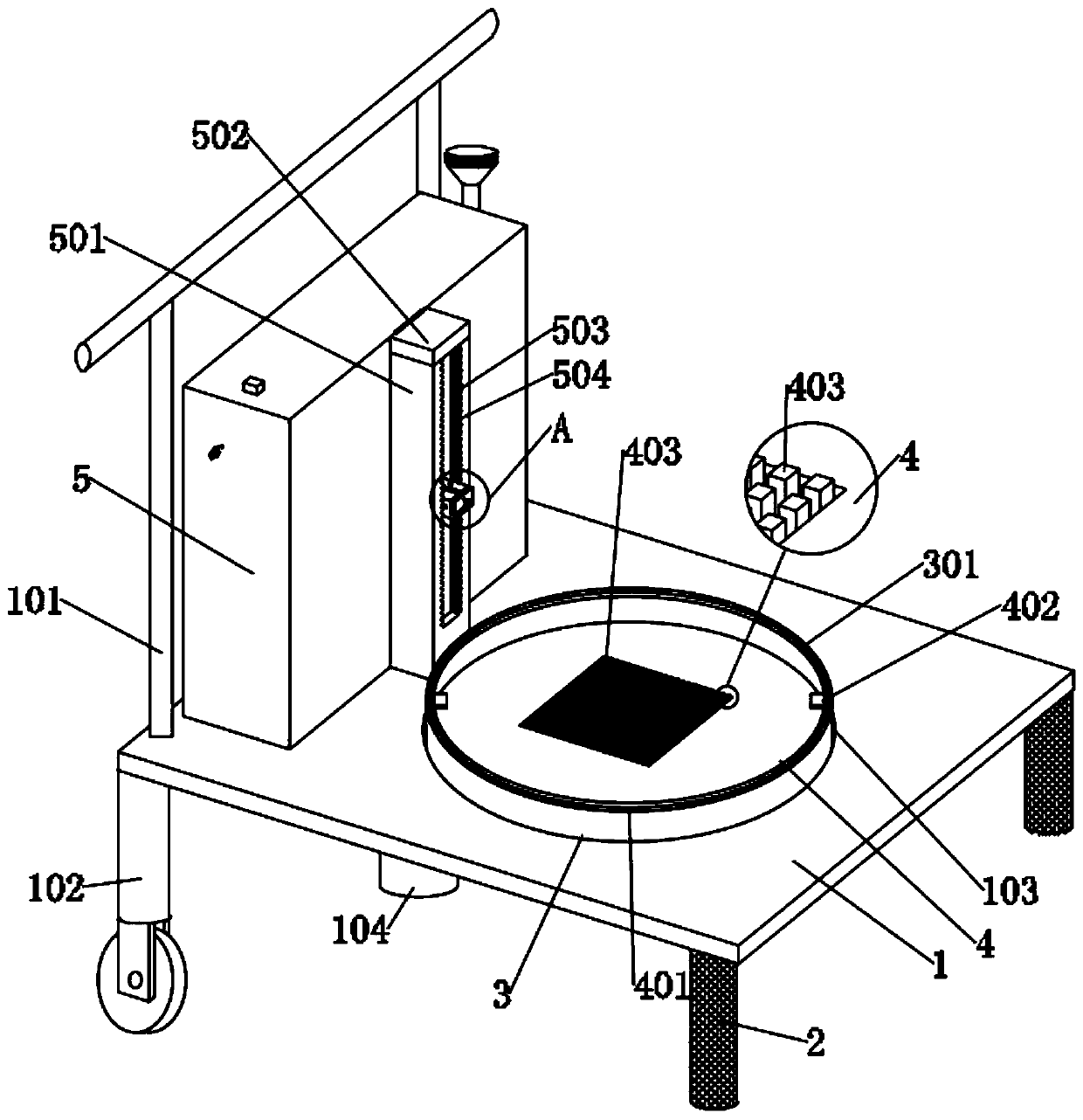

Image

  • Spraying machine for machining and producing automobile parts
  • Spraying machine for machining and producing automobile parts
  • Spraying machine for machining and producing automobile parts

Examples


Embodiment

[0030] As attached figure 1 Attached Figure 8 Shown:

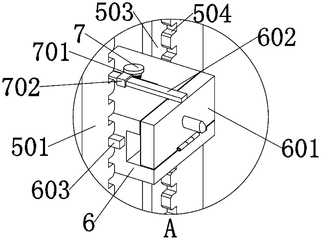
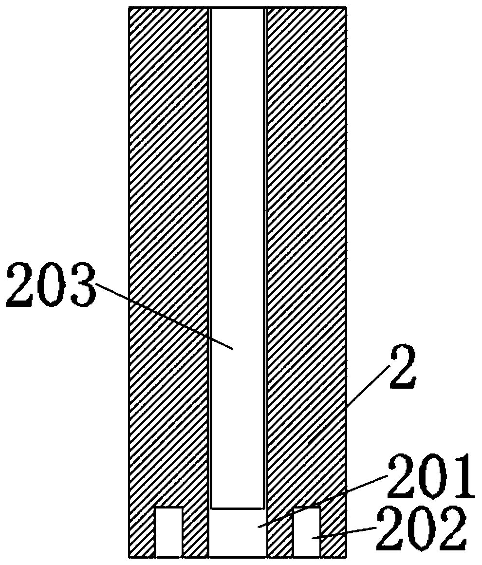
[0031] The present invention provides a spraying machine for the processing and production of auto parts, including: a main body 1, a push rod 101, a supporting leg 102, a rotating bin 103, a motor 104, a transmission gear 105, a front leg 2, an inner groove 201, a buffer Slot 202, support rod 203, rotating part 3, enclosure 301, force tooth 302, moving part 4, insertion plate 401, manual plate 402, support block 403, storage compartment 5, adjusting part 501, closing plate 502, sliding groove 503, limiting slot 504, moving head 6, turning head 601, shrinking plate 602, limiting block 603, external support spring 604, top plate 7, rotating rod 701 and stopper 702; main body 1 is a rectangular plate structure, and the main body A push rod 101 is installed at the left edge of the top end of the main body 1 by welding, and a supporting leg 102 is fixedly installed at the left edge of the bottom end of the main body 1, and a ro...


PUM


Abstract

The invention provides a spraying machine for machining and producing automobile parts. The spraying machine comprises a closing plate, a sliding groove, a limiting groove, a moving head, a turning head, a contraction plate, a limiting block, an outer supporting spring, a top plate, a rotating rod and a blocking piece; the rear end of the moving head is connected with the interior of a storage binthrough a transmission pipeline; embedded blocks are arranged on the two sides of the moving head; and the embedded blocks are embedded and mounted in the sliding groove. Clamping teeth on the outerside of the rotating rod are connected with the side edge of the contraction plate, and a rotating piece here is used for receiving the power transmitted by a motor so as to drive the moving piece torotate with parts inside the moving piece, so that the parts can be rotatably sprayed, the spraying is uniform; and an enclosure at the top end of the rotating piece is used for mounting the moving piece, so that the moving piece can drive the parts to rotate, and when spraying dye is wet, the parts can be taken out by taking out the moving piece and dried, and other moving pieces can be placed atthe spraying machine.

Description

Technical field [0001] The invention belongs to the technical field of parts spraying machines, and more specifically, relates to a spraying machine used for processing and producing automobile parts. Background technique [0002] In the process of automotive parts processing, it is usually necessary to color the parts before they can be used. At this time, a spraying machine is required to dye them. [0003] Based on the equipment in the prior art, it has been discovered that the existing auto parts spraying machine does not have a perfect structure to control the spraying uniformity when spraying, and it is not convenient to control the parts to be sprayed evenly, and the existing auto parts spraying machine is adjusting The structure of the spray angle of the spray head is not perfect, and it is not convenient to adjust the spray angle according to the demand. Summary of the invention [0004] In order to solve the above technical problems, the present invention provides a spray...

Claims


Application Information

Patent Timeline
Patent Type & Authority Applications(China)
IPC IPC(8): B05B13/02B05B15/68
CPCB05B13/0228B05B15/68
Inventor 金义凯
Owner 广德中晨电子科技有限公司
Learn More