A protective fence device for a road bridge
A technology of enclosure devices and road bridges, which is applied to road safety devices, roads, fences, etc., can solve the problems of general fixing effect, small warning range, and affect the appearance, and achieves improved warning range, height of the device, and increased visibility. effect of sight distance
- Summary
- Abstract
- Description
- Claims
- Application Information
AI Technical Summary
Problems solved by technology
Method used
Image

Examples
specific Embodiment approach 1
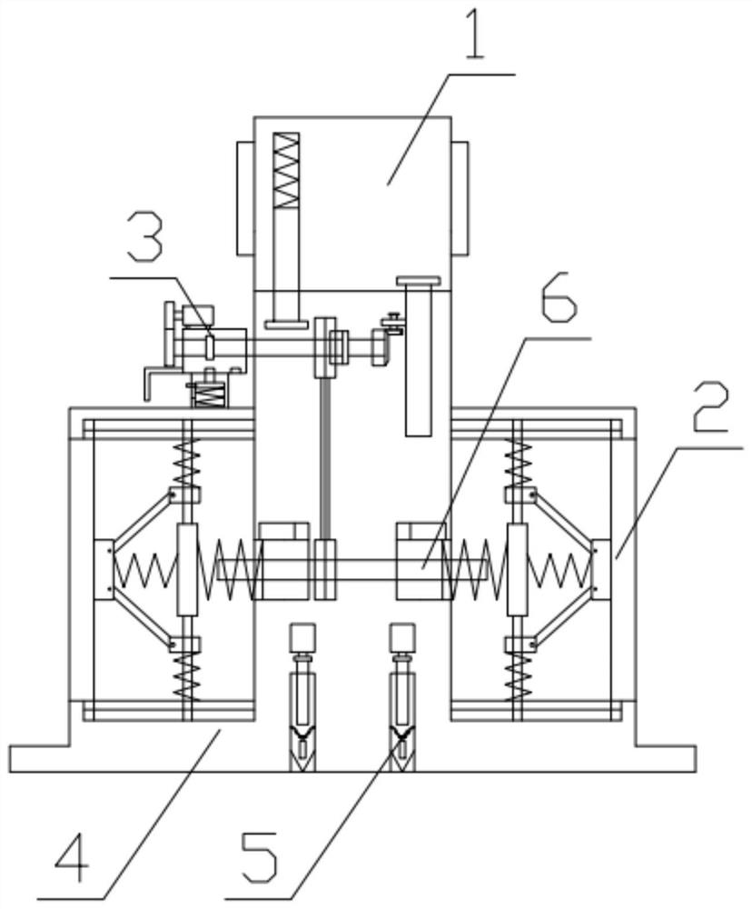
[0041] Combine below figure 1 Description of this embodiment, a protective enclosure device for a road bridge, including a warning mechanism 1, a buffer mechanism 2, a control mechanism 3, a device base 4, a stabilizing needle 5, and a buffer adjustment mechanism 6, characterized in that: the warning mechanism 1 is located above the device base 4, the warning mechanism 1 is connected to the device base 4, the buffer mechanism 2 is located on both sides of the device base 4, the buffer mechanism 2 is connected to the device base 4, and the control mechanism 3 is installed inside the device base 4, The control mechanism 3 is connected with the device base 4, the buffer adjustment mechanism 6 is located at the bottom of the control mechanism 3, the control mechanism 3 is connected with the buffer adjustment mechanism 6, the buffer adjustment mechanism 6 is installed inside the device base 4, the buffer adjustment mechanism 6 is connected with the buffer The mechanism 2 is connect...
specific Embodiment approach 2
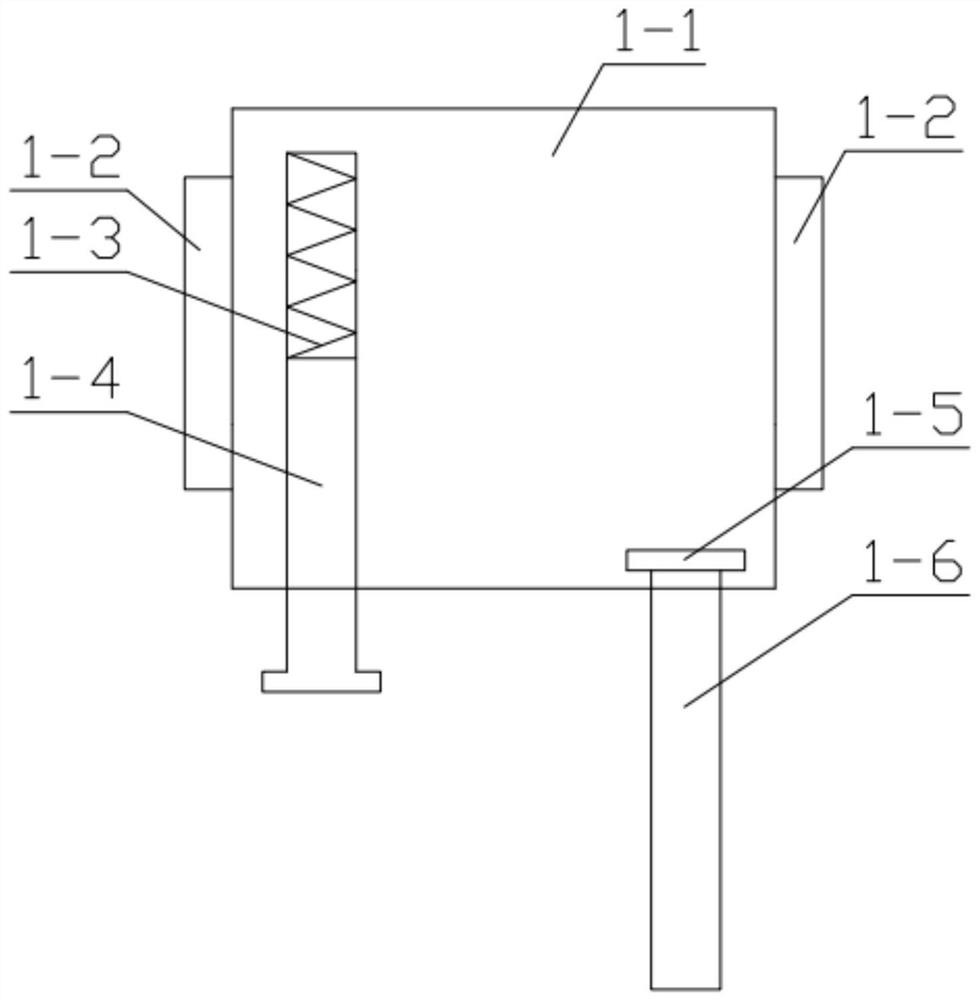
[0045] Combine below figure 2 Describe this embodiment, this embodiment will further explain the first embodiment, the warning mechanism 1 includes a lifting head 1-1, a warning sign 1-2, an inner connection spring 1-3, an auxiliary limit post 1-4, Circular part 1-5, worm 1-6, warning signs 1-2 are installed on both sides of lifting head 1-1, inner connecting spring 1-3 is located in the groove of lifting head 1-1, inner connecting spring 1 -3 is fixedly connected with the lifting head 1-1, and the inner connection spring 1-3 is fixedly connected with the auxiliary limit column 1-4, and the auxiliary limit column 1-4 is connected with the lifting head 1-1 through the gap of the groove, and the lifting The head 1-1 is connected with the round part 1-5 through the gap of the groove, and the round part 1-5 is fixedly connected with the worm 1-6; the worm gear 3-8-2 drives the worm 1-6 to rotate upwards, so as to realize the lifting head The purpose of the part 1-1 rising, the a...
specific Embodiment approach 3
[0047] Combine below Figure 5-10 Describe this embodiment, this embodiment will further explain the first embodiment, the control mechanism 3 includes a motor 3-1, a motor gear 3-2, a connecting square shell 3-3, a first control spindle 3-4, an L-shaped Handle 3-5, position fixing structure 3-6, main connecting wheel 3-7, lifting gear group 3-8, gear chain 3-9, motor 3-1 is fixedly connected with motor gear 3-2, motor 3-1 and The connecting square shell 3-3 is fixedly connected, and the connecting square shell 3-3 is connected with the first regulating main shaft 3-4 through a through hole, the motor gear 3-2 is meshed with the first regulating main shaft 3-4, and the L-shaped handle 3- 5 is fixedly connected with the connecting square shell 3-3, the connecting square shell 3-3 is connected with the fixed position structure 3-6 through a groove, the first control spindle 3-4 is connected with the main connecting wheel 3-7 through a through hole gap, The first regulating main...
PUM
 Abstract
Description
Claims
Application Information
 - R&D
- Intellectual Property
- Life Sciences
- Materials
- Tech Scout
- Unparalleled Data Quality
- Higher Quality Content
- 60% Fewer Hallucinations
Browse by: Latest US Patents, China's latest patents, Technical Efficacy Thesaurus, Application Domain, Technology Topic, Popular Technical Reports.
© 2025 PatSnap. All rights reserved.Legal|Privacy policy|Modern Slavery Act Transparency Statement|Sitemap|About US| Contact US: help@patsnap.com