Sliding-plug door

A technology for door panels and door locks, applied in door/window accessories, electric locks, power transmission/actuator features, etc., can solve problems such as poor door sealing, increased costs, and potential safety hazards

Pending Publication Date: 2019-11-29
金湖县微晶控制系统有限公司
View PDF0 Cites 2 Cited by
  • Summary
  • Abstract
  • Description
  • Claims
  • Application Information

AI Technical Summary

Problems solved by technology

However, this kind of door lock structure has great safety hazards, because when the vehicle is running, the road surface is bumpy and hollow, and the guide wheel on the door lock will roll back and forth in the guide rail, which will lead to poor sealing of the door. When running at high speed, the airflow will enter the car from the gap in the door, which will affect the ride experience of the passengers; when the vibration is large, the guide wheels will even slide out from the original path in the guide rail, which will cause the door to be opened automatically. big security risk
[0004] There are also some Sierra door locks that can avoid the problem of automatic opening of the car door during vibration and bumps, but usually the opening and closing of the car door and the locking and unlocking of the door lock require a driving mechanism respectively, that is, the entire set of car doors requires at least two sets of drive motors. One set is used to drive the locking and unlocking of the door lock, and the other set is used to drive the opening and closing of the car door, which undoubtedly increases the cost and the structure of the car door is complicated

Method used


Image

  • Sliding-plug door
  • Sliding-plug door
  • Sliding-plug door

Examples


Embodiment approach 1

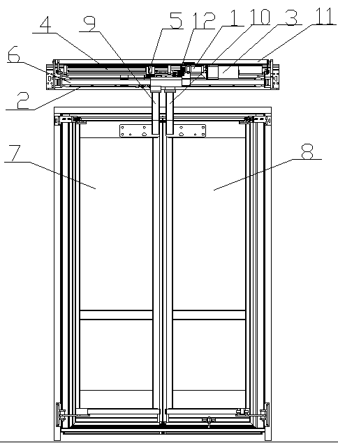
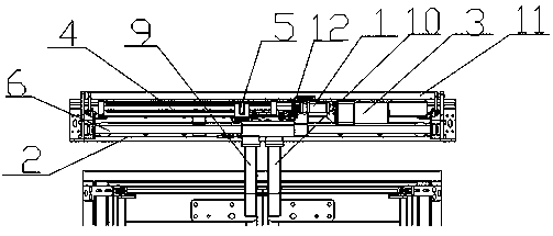
[0065] This embodiment provides a double sliding door, such as Figures 1 to 9 As shown, it mainly consists of door lock clutch device 1, door panel synchronization device 2, drive motor 3, lead screw 4, guide rail 48, lead screw nut 5, first door panel 7, second door panel 8, first door frame 9, the first Two door frames 10, the first slide bar 6 and the second slide bar 49 are formed, the drive motor 3 is fixed on the tray 11 of the sliding door, the first slide bar 6 and the second slide bar 49 are arranged parallel to each other and both ends are Fixed on both sides of the tray 11, the first slide bar 6 and the second slide bar 49 are arranged in parallel with the lead screw 4 and are located below the lead screw 4. One end of the lead screw 4 is rotationally connected with one side of the tray 11, and the other end is connected with the lead screw 4. The locking stopper 12 is coaxially fixed, and the lead screw 4 is horizontally located directly above the first door panel...

Embodiment approach 2

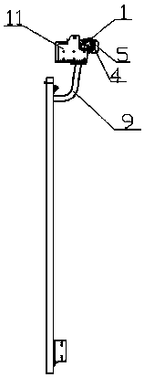
[0088] This embodiment provides a single sliding door, such as Figure 30 and 31 As shown, the single-sliding door is roughly the same as the double-sliding door in Embodiment 1, the only difference is that the single-sliding door has only one door panel, one door frame, one sleeve, one sliding rod and no door panel synchronization Device, its door panel is closed and locked and the process of unlocking and opening is basically the same as that of the double plug door, and will not be repeated here.


PUM


Abstract

The invention relates to the field of sliding-plug door locks, and discloses a sliding-plug door. When a door panel is closed, a drive motor drives a lead screw to rotate forwards, a lead screw nut moves along the lead screw in a straight-line mode to drive a sleeve to move along the door panel located at the bottom parts of a sliding rod and a door carrying frame in a straight-line mode, when thesleeve moves to be in contact with a door lock clutch device, the door lock clutch device is driven to clamp to and lock with a to-be-locked stopper which is coaxially fixed to the lead screw, and closing and locking of the door panel are realized; when the door panel is opened, the drive motor drives the door lock clutch device to separate from the to-be-locked stopper, and the to-be-locked stopper after separation rotates backwards under continuous driving of the drive motor to drive the lead screw to rotate backwards, the lead screw nut moves along the lead screw in a straight-line mode and in a reversed direction, and so that the sleeve drives the door carrying frame to move in a reversed direction, and whenthe sleeve moves in the reversed direction to separate from a door lock clutchmechanism, the lock clutch mechanism returns to an original state. Locking and unlocking of a door lock and opening and closing of the door panel in the sliding-plug door share the common driving motor, so as to avoid automatic opening of a vehicledoor in bumpy operation, and the vehicle door has good airtightness.

Description

technical field [0001] The invention relates to the field of sliding door locks, in particular to a sliding door. Background technique [0002] At present, bus doors, subway doors or high-speed rail doors usually use sliding doors. The sliding door has good sealing performance and takes up less space, making the overall model beautiful and generous. The quality of the sliding door lock directly affects the quality of the sliding door. Security and sealing, in order to improve the security of sliding door, the researcher in the field mainly puts the object of research on the structure of sliding door lock. [0003] The currently used plug-in door lock structure is usually when the door is closed, a guide wheel on the door lock is introduced into the guide rail through a guide rail on the vehicle frame, and the movement of the door lock is restricted by this guide rail, and the door lock is fixed on the On the door, so that the movement of the door is restricted, so as to ach...

Claims


Application Information

Patent Timeline
IPC IPC(8): E05F17/00E05F15/652E05B81/06E05B81/40E05B81/16E05B77/00E05B83/36
CPCE05F17/004E05F15/652E05B81/06E05B81/40E05B81/16E05B77/00E05B83/36E05B83/363E05F2017/005E05Y2900/531E05Y2900/51E05Y2900/506
Inventor 吕思华郑善友
Owner 金湖县微晶控制系统有限公司
Why Eureka
Try Eureka