Circularly polarized medium reflector unit and reflectarray antenna based on 3D printing technology
A reflection unit, 3D printing technology, applied in antennas, antenna arrays, specific array feeding systems, etc., can solve the problem of not being able to realize circular polarization characteristics and processing of dielectric reflection array antennas at the same time, and achieve suppression of multipath effects, High precision and excellent performance
- Summary
- Abstract
- Description
- Claims
- Application Information
AI Technical Summary
Problems solved by technology
Method used
Image
Examples
Embodiment 1
[0026] In recent years, with the rapid development of mobile communication technology, both radar and communication systems expect antennas to have more functionality and adaptability. The microstrip reflectarray antenna has some advantages of the reflector antenna and the large phased array antenna, and has been widely used and continuously improved. However, the traditional microstrip reflectarray antenna has a small phase range, narrow gain bandwidth, complex structure, and limited application range; the dielectric reflectarray antenna has a large phase range, simple structure, and easy processing. Circularly polarized antennas can suppress multipath effects, so circularly polarized dielectric reflectarray antennas have received great attention. However, the dielectric reflectarray antenna using low dielectric constant materials cannot achieve circular polarization, and the dielectric reflectarray antenna using high dielectric constant materials cannot be processed.
[002...
Embodiment 2
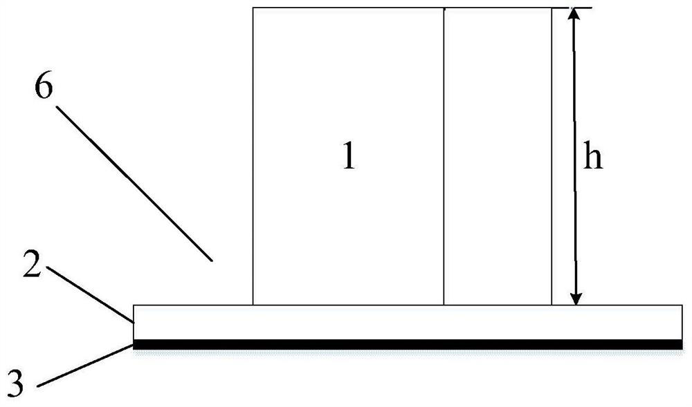
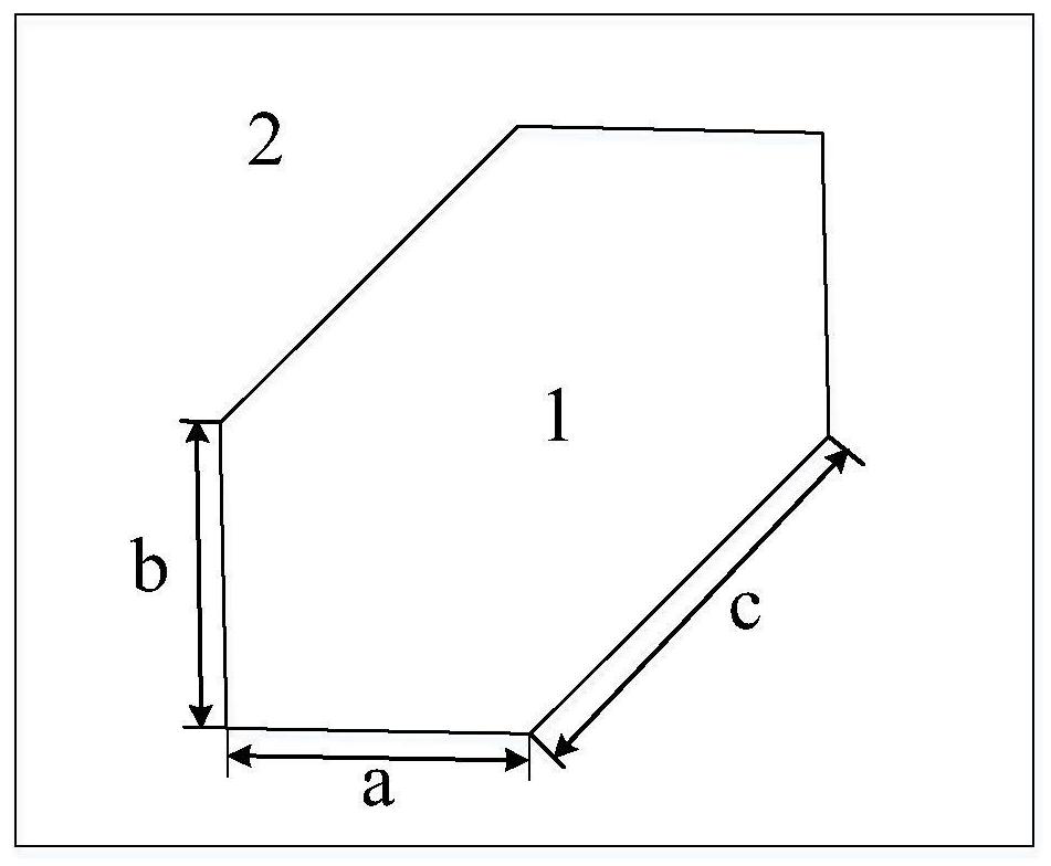
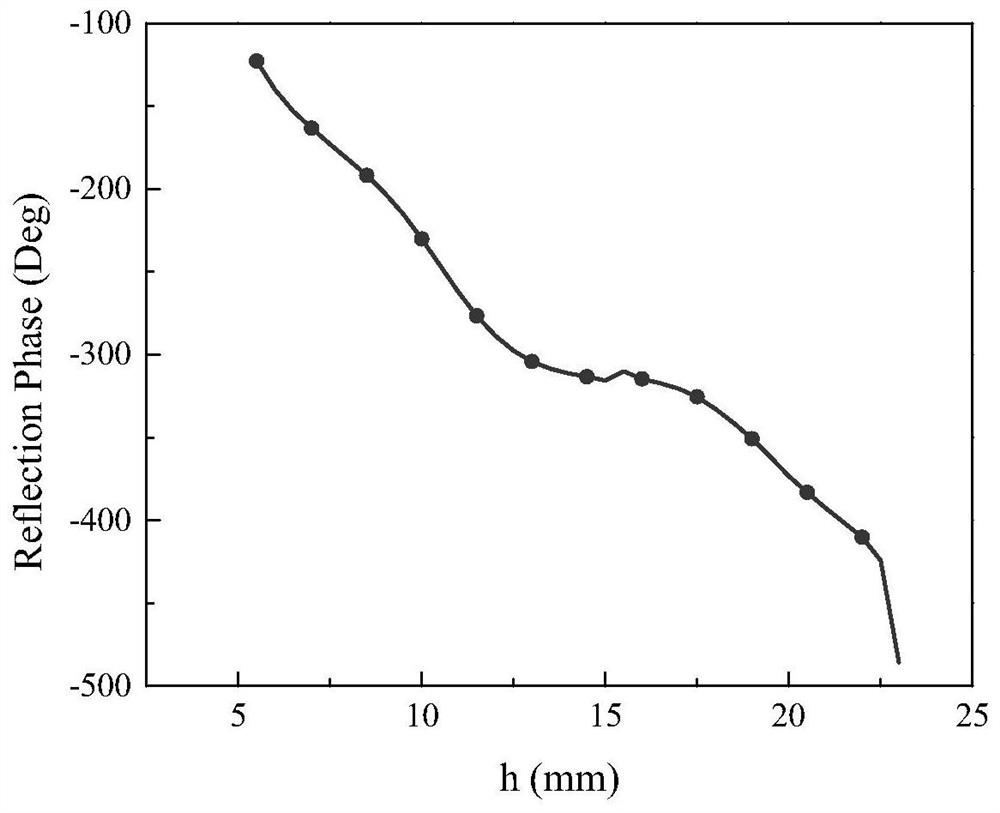
[0031] The overall composition and specific structure of the circularly polarized medium reflective unit based on 3D printing technology are the same as in Embodiment 1, see figure 2, the side length a of the dielectric block 1 is selected between 4.5mm~5mm, the side length b is also selected between 4.5mm~5mm and the side length c is selected between 5.8mm~6.8mm, in the present invention a =b. The reflective unit 6 is set at a period of 12 mm to 20 mm. see image 3 , the height h of the dielectric block 1 of the present invention changes from 5.5mm to 23mm, and the reflection phase of the dielectric reflection unit 6 changes from -123° to -486° accordingly. In the present invention, there is a one-to-one correspondence between the height of the dielectric block 1 and the reflection phase. In this embodiment, a=b=5mm, c=5.8mm, and the reflection unit 6 period is set to 12mm, which is mostly used in situations where the antenna aperture efficiency is required to be high.
...
Embodiment 3
[0034] The overall composition and specific structure of the circularly polarized medium reflection unit based on 3D printing technology are the same as those in Embodiment 1-2, see figure 2 , the side length a of the dielectric block 1 is selected between 4.5mm~5mm, the side length b is also selected between 4.5mm~5mm and the side length c is selected between 5.8mm~6.8mm, in the present invention a =b. The reflective unit 6 is set at a period of 12 mm to 20 mm. see image 3 , the height h of the dielectric block 1 of the present invention changes from 5.5mm to 23mm, and the reflection phase of the dielectric reflection unit 6 changes from -123° to -486° accordingly. In the present invention, there is a one-to-one correspondence between the height of the dielectric block 1 and the reflection phase. In this embodiment, a=b=4.5mm, c=6.8mm, and the period of the reflection unit 6 is set to 20mm, which is mostly used in situations where circular polarization is highly required...
PUM
| Property | Measurement | Unit |
|---|---|---|
| height | aaaaa | aaaaa |
| thickness | aaaaa | aaaaa |
Abstract
Description
Claims
Application Information
 - R&D
- Intellectual Property
- Life Sciences
- Materials
- Tech Scout
- Unparalleled Data Quality
- Higher Quality Content
- 60% Fewer Hallucinations
Browse by: Latest US Patents, China's latest patents, Technical Efficacy Thesaurus, Application Domain, Technology Topic, Popular Technical Reports.
© 2025 PatSnap. All rights reserved.Legal|Privacy policy|Modern Slavery Act Transparency Statement|Sitemap|About US| Contact US: help@patsnap.com


