
Pneumatic tire

A technology for pneumatic tires and bead cores, applied to tire parts, bead edges, yarns, etc., can solve the problems of no enlightenment, no teaching of bead cores, etc., and achieve the goal of improving fatigue resistance, ensuring strength and fatigue resistance Effect

Active Publication Date: 2019-11-29
THE YOKOHAMA RUBBER CO LTD
View PDF16 Cites 3 Cited by
  • Summary
  • Abstract
  • Description
  • Claims
  • Application Information

AI Technical Summary

Problems solved by technology

However, these documents do not suggest applying the above-mentioned rubber reinforcing cord to a specific member such as a bead core, and furthermore, do not teach specific requirements for application to the bead core at all.

Method used

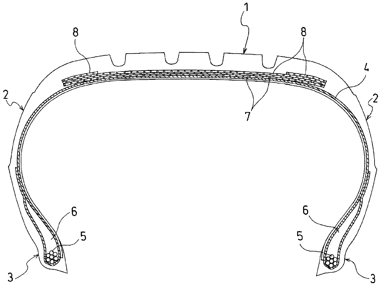
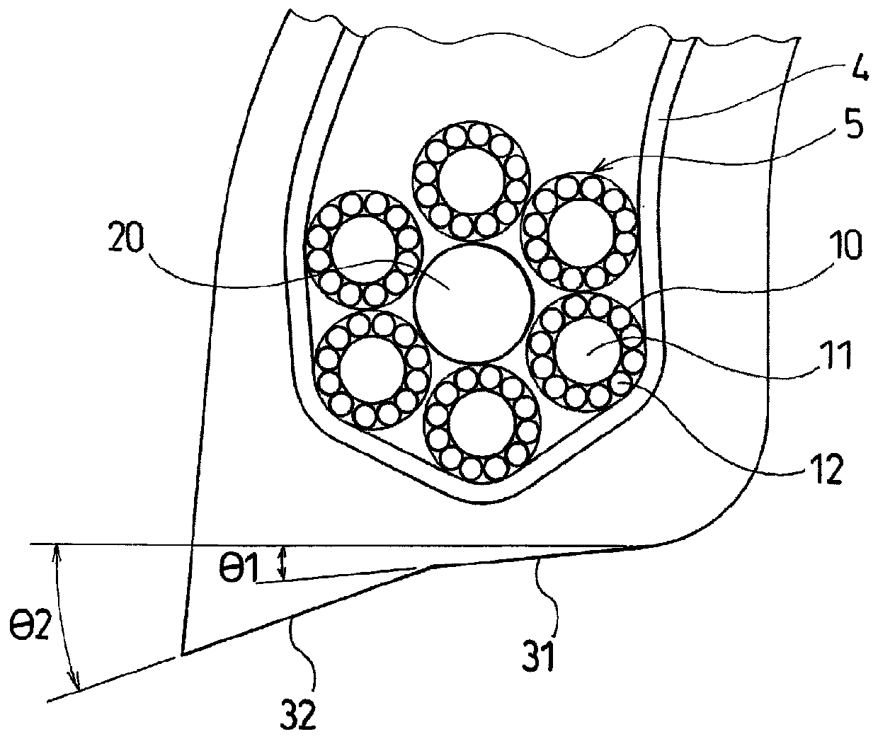
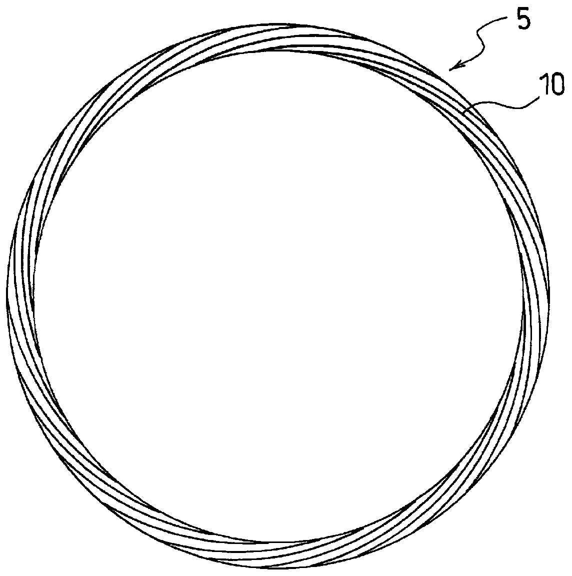

Image

  • Pneumatic tire
  • Pneumatic tire
  • Pneumatic tire

Examples


Embodiment

[0059] In a pneumatic tire having a tire size of 205 / 55R16, including an annular bead core embedded in the bead portion and a carcass layer locked to the bead core, a tire with only the structure of the bead core being different was produced. Tires of Conventional Example 1, Comparative Examples 1-2, and Examples 1-3.

[0060] In Conventional Example 1, a bead core having a stacked bead structure having a hexagonal cross-section was used, and a steel wire was used as the wire material. In Comparative Example 1, a bead core having a stacked bead structure having a hexagonal cross-section was used, and a composite cord including a core wire made of carbon fibers and a plurality of side wires made of glass fibers arranged around the core wire was used. wire as its wire. In Comparative Example 2, a bead core having a cable bead structure was used, and carbon fiber cords were used as the core and side wires.

[0061]In Example 1, a bead core having a cable bead structure was used...


PUM


Abstract

Provided is a pneumatic tire that can exhibit performance similar to or exceeding that of the prior art, while weight is reduced using a composite cord comprising a material other than a metal in a bead core. A pneumatic tire comprising an annular bead core (5) embedded in a bead part (3), and a carcass layer (4) interlocked in the bead core (5), wherein the bead core (5) has a cable bead structure in which a composite cord (10), which includes core wires (11) comprising carbon fibers and a plurality of side wires (12) comprising glass fibers and disposed around the peripheries of the core wires (11), is wound into a helical formation around an annular core (20).

Description

technical field [0001] The present invention relates to a pneumatic tire including an annular bead core embedded in a bead portion and a carcass layer locked to the bead core. Pneumatic tires that achieve performance equal to or better than conventional ones while achieving weight reduction using composite cords. Background technique [0002] A pneumatic tire generally includes a carcass layer stretched between a pair of bead portions. In addition, an annular bead core is embedded in the bead portion, and the carcass layer is wound around the bead core from the inner side of the tire to the outer side and locked to the bead core. [0003] Conventionally, as the bead core of a pneumatic tire, a laminated bead in which one or more steel wires are continuously wound in layers along the tire circumferential direction, or a ring-shaped core made of steel wires has been used. A cable bead (English: cable bead) formed by helically winding side wires composed of other steel wires ...

Claims


Application Information

Patent Timeline
Patent Type & Authority Applications(China)
IPC IPC(8): B60C15/04B60C15/024
CPCB60C15/04B60C2015/042B60C2015/046D07B1/0613D07B2501/2053D02G3/48D07B2205/306D07B2201/2059D10B2101/06D10B2101/12D07B2801/14D07B2801/24B60C15/024B60C15/05
Inventor 张替绅也
Owner THE YOKOHAMA RUBBER CO LTD
Learn More